- +27 12 644 0300
- +44 1234 834920
-
This email address is being protected from spambots. You need JavaScript enabled to view it.
Installation & Troubleshooting
Answers to common installation queries
Caddie Licence Activation |
||
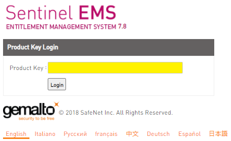
Easy Guide to activating your Caddie software licence.Congratulations on the purchase of your Caddie software licence. You should by now have received an activation email providing you with a link to the licence activation page, and the Product Key(s) for your Caddie licence(s). If you have not received your email yet, then please check the Inbox for the email address you provided at the time of purchase, 'Clutter', 'Junk email' and/or Spam folders first, then contact support@caddiesoftware.com for assistance if the email cannot be found. Once you have located your Caddie licence activation email follow this three step guide to activate your Caddie licence. 1.Download the Caddie software Before activating your free licence, you will first need to download and install the Caddie software program (otherwise you have nothing to activate). Now that you have activated your licence(s), download the Caddie install file via the link below, saving the file to your ‘Downloads’ folder or other suitable file location: 2. Install the Caddie program Once the download is complete, ‘Run’ the downloaded file to start the installation. Follow the on-screen prompts, accepting the terms and conditions, and clicking the ‘Next’ buttons when prompted to continue. Once the installation is complete, click the, ‘Finish’ button to close the install dialogue. The Caddie software program is now installed on your computer. 3. Activate your Free Caddie licence Follow the link to the licence activation page, https://licensing.caddiesoftware.net:446/ems/customerLogin.html
Enter the Product Key included with the activation email into the Product Key field on the login dialogue (here shown yellow) Then click ‘Login’ On the page that loads, click the, ‘Online Activation’ button to activate your Caddie licence.
For more information on activating your Caddie licence, watch the Caddie Licence Activation Video included below...
Further Links and Information What's New VideosThe feature focus videos are a brilliant way to discover what's new in Caddie 26, displaying the functionality, many showing the new tools and features in real-world type scenarios, watch the videos HERE Discover the new Caddie GIS Application The Caddie GIS App provides easy access to Geographic Information System (GIS) data covering, mapping, infrastructure buildings and roads, as well as details of local services, amenities, flooding, population and more. Access data directly from sources including, • Bing and Google Mapping • OpenStreetMap • Ordnance Survey • And UK Government Data Providing the unique ability to port GIS data directly into everyday Caddie .dwg drawings, the Caddie GIS is for those wishing to create informed and substantive designs without the need to invest in expensive alternative software and time-consuming data reformatting. |
 |
International Sales UK +44 (0) 1234 834920 email: sales@caddie.co.uk |
|
South Africa Sales SA +27 (0) 12 644 0300 email: sales@caddie.co.za |
|
Online Training |
 |
Learn More... |
 |
Caddie Educational *FREE for Students and Educators |
| *Caddie Educational is FREE for Students and Educators at qualifying institutions (non-commercial use) | |
| All trademarks acknowledged | |
Applies to
Caddie 17 build 2 and later
Question
How can I import a screen layout from a previous version of Caddie?.
Solution
Caddie 17 build 2 has a new direct import of screen layouts from Caddie 16. After installing Caddie 17 you will be asked if you want to migrate your settings from a previous version. If you select 'Yes', one of the options will be to import your screen layout.
If you have already been past this step and resplied 'No', you can get back to this option at any time by going to Utilities -> System -> Migrate Settings from Caddie 16.
Note that this option is only valid for importing settings from the previous major release of Caddie.
If a previously working Caddie says 'Softlock not in use, or is expired' there may be several causes.
1. The softlocks are time limited and may have expired
2. Caddie may be unable to communicate with the softlock due to firewall issues etc. (Caddie requires port 1947 to be open)
3. The Sentinel Hasp license manager may have stopped
To check if the licence manager is stopped, From the start menu type services.msc into the search box and the services dialogue should open. Scroll down to find Sentinel Local License Manager and ensure it is running. If not select it and click the Start option. Close the services dialogue and restart Caddie.
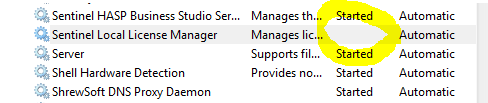
Alternatively, restart the PC and the license manager should be restarted automatically.
Applies To:
Caddie 16 onwards
Windows Vista, Windows 7
Question:
I try to save a screen layout and I get the message there is no layout to save. What is the problem?
or
I try to import a screen layout, but nothing changes, why?
Answer:
This is usually only with a 64 bit operating system and is usually due to the security settings on your computer.
In order to save a screen layout or to import a screen layout, Caddie must be run as an administrator. To do this run Caddie by right clicking the Caddie launch icon from the Start | Programs menu and choose 'Run As Administrator'.
Note:
You can not do this from a pinned icon on the Quick Launch bar.
Applies To
No specific operating system or Caddie version
Question
When I download Caddie, which is a very large file, my connection sometimes breaks and I have to start all over again. I also have a very slow connection and I would like to speed this up and have the ability to break the download up into small chunks. Is there a way to do this.
Answer
Yes there is a way to do all of these things. What you need is to download and install one of the many download accelerators or download managers. There are many available. Some have to be paid for, some have free limited use and some are totally free. Even the paid for versions usually have a free trail period. Some work standalone and some will be installed as add-ons for your favourite internet browser.
Which ever you choose they all will resolve the three main requirements.
Speed up the download time.
Whilst these programmes don't really speed up the download, what they do is to make more than one download connection and split the download over these connections and reasemble it after the download. The net result is a faster download.
Restart the download without restarting from the beginning again
Because they way these accelerators work, they are able to recognise how much of the download has been made, so that in case of connection breaks, a restart will first check the position of the previous download and restart from that position. So in other words, if 80% had been downloaded then when a download of the same file is down only the last 20% will need to be downloaded.
Pause the download
Similar to the last requirement, the download can be paused and then resumed at a later time.
In addition some will even send you computer to standby, hibernate or even shutdown, so you can leave it running and when it is finished downloading your computer will do what ever you have selected.
What one you use will be up to your personal preference.
Here are a couple to lookout for.
![]()
Speedbit home page
DAP can be integrated with various browsers such as Microsoft IE, Firefox, Google Chrome, Opera and Netscape.
This seems to be the web favorite.
![]()
IE6,IE7,IE8 and Firefox are supported
For Google Chrome users there is this extension
NOTE
After a downloading check the size of the downloaded file matches what is stated on the Caddie site. If the size if different from that stated, i.e it is too small, it is probable due to a firewall not allowing access to the download. This can be rectified either by setting your firewall to allow your download manager to connect automatically or temporally unblock you firewall.
ACS (Caddie) does not endorse any of these or other download accelerator products and therefore can not offer support for them. Please use the providers sites for support.
APPLIES TO
Caddie 16 and above
QUESTION
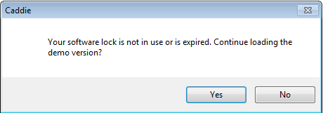
I am a registered user of Caddie but when I run a newly installed Caddie I get a Message saying:
"No Dongle found or you are not authorized to use it.
Continue loading the DEMO version?"
ANSWER
You may get this message for a number of reasons.
- You installed a copy of Caddie that didn't recognise your dongle.
- You are not licensed to use this version.
- If you have a dongle it is un-plugged.
- The Dongle has not been correctly installed.
If you have a USB dongle check that it is lit.
From Caddie 16 a new Dongle driver is used. This new driver is compatible with all USB dongles and some later Parallel Port dongles. If your parallel port dongle has the embossed word "HASP" followed by a registration mark then it will need to be changed. If after following these instruction you still have problems, contact Caddie support.
- You are not authorised for this version of software.
IMPORTANT
If you have a dongle but haven't plugged it it, cancel Caddie, plug the dongle in and restart Caddie.
If you are using Windows Vista, Windows 7 or Windows 8 run Caddie.in 'Administrator Mode'. To do this right click the Caddie icon and select 'Run As Administrator'.
If using Windows XP, just run Caddie.
In all cases run Caddie in demo mode. Caddie will check that the dongle and the licence file match. If they don't you will be invited to download the latest security file.
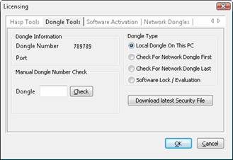
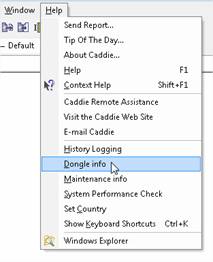
You will be taken to the 'MENU | HELP | DONGLE INF dialogue.
If the dialogue isn't displayed, use the Help menu to open it.
If the dongle driver has been installed correctly, you should see the number of your dongle mentioned.
If it has a number
If you have a dongle select the ”Download Latest Security File” button. Once done you will get the following message.
Select 'YES' and Caddie will restart in the mode you are licensed for.
Your firewall or your Windows security may block the automatic replacement of the file. You will have to first remove the existing one manually. To do this go to ’MENU | | HELP | WINDOWS EXPLORER’. This should open Windows Explorer at the Caddie folder. Find a file called MSDBUTILS.DLL and delete it. Now try the ”Download Latest Security File ” again.
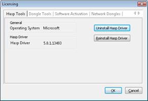
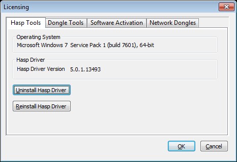
If dongle number is blank If you have a Dongle and it is plugged in and lit, run the ”Uninstall Hasp Driver” followed by a ’Reinstall Hasp Driver’ from the ’Hasp Tools’ Tab. Note the driver installed should be as shown or higher.
Key Words
Dongle, HASP, Caddie, Demo, Installing, CAD.
SUBJECT LIST
Introduction
Installing Caddie
Installing Vio
Running Caddie for the First Time
What To Do If Caddie Runs in Demo Mode
Updating the Dongle Security Key
Mainenance Date Is reported Incorrectly
Installing Network Dongles
INTRODUCTION
Please read the following guide before installing Caddie.
Using the standard options, the installation of Caddie should be straight forward.
The installation process will vary depending on the license you have. There are three types of license:
- Softlock License
The period of the license can be purchased. This is issued for a short term rental of Caddie or a Student license. At the end of the time period the license will revert to Demo
If no time has been purchased the license is Evaluation and lasts for 14 days. After 14 days the license reverts to DEMO. It can be converted to any other license at any time.
The licence for a softlock is a one off per computer, regardless of software version, and is not transferable between computers.
- Hardware License (Dongle / HASP)
Full Caddie, needs a Hardware key which also needs an additional driver to be installed (see below)
- Network License (Network Dongle / HASP)
Needs a special hardware key and additional License Manager software to be installed on the Network Dongle Server. This is covered at the end of this document.
Evaluation - The Evaluation license lasts for 14 days. Caddie will automatically be in Evaluation when Caddie runs for the first time or is the selected license.
Demo is a full installation without the requirement of any hardware or software license. The only limitation is the ability to save or copy drawings or drawing elements (including backups). Caddie will run in ‘DEMO’ mode when:
- The Softlock 14 day evaluation period has finished
- A hardware dongle is not present at the time of Caddie loading or it has been removed with Caddie running. Note if the dongle has been removed or has failed to work dure to system reasons, Caddie will need to be re-started with the dongle in place and working.
- The hardware dongle has not been authorised
- There are no more Network licenses available
- Incorrect HASP driver has been installed
INSTALLATION
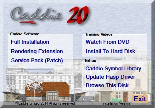
INSTALLING CADDIE
Full Instalation
From the dialogue, select Full Installation and follow the installation prompts and do a Typical installation. Caddie also requires some Microsoft TM Operating System files to be downloaded and installed. This will be done automatically so let caddie do this. If these are blocked by your fire wall or not run, Caddie will not run correctly.
Redering Extrension
This is normally installed at the same time as Caddie. If it need to be installed separately from the dialogue, select Rendering Extension to install Caddie Vio photo-realistic rendering integrated into Caddie Professional.
Symbol Library
You will normally be asked if you want to install the symbol library. If it needs to be installed separately, this can be done by selecting Caddie Symbol Library from the menu.
Training Videos
From the dialogue, select Install To Hard Disk to install the Caddie training videos.
Note these training videos are on the Installation disk and not the What’s new video disk. The Video disk is designed to play from a standard video recorder or a computer with the correct programme and drivers. Additional drivers for a computer can be found by “Browsing This Disk” from the installation menu and running the file in the “VLC” folder.
RUNNING CADDIE FOR THE FIRST TIME
Plug Dongle In
(Skip this step if you have an Evaluation or a Time limited license.)
If you have been provided with a Dongle Key (HASP) then now is the time to plug it in. Insert the dongle into a convenient USB socket and wait for it to light.
Run Caddie
When Caddie runs for the first time there are a number of settings that need to be finalised so you will see the following dialogue.
(If this is a Caddie 18 reinstall, this step maybe ignored so go to “What to do if Caddie runs in Demo Mode”)
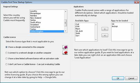
- Select your region
- Select the License type.
Choose one of the following depending which licence you have (the introduction explained the various licence types).
- I have a Dongle Key (HASP) choose
‘I have a dongle connected to this computer’
- I have a network dongle choose
‘I connect to a network dongle on another computer’
(see separate instructions for installing a network dongle).
- I have a time limited license (softlock), you will not have a dongle and you will have an activation code choose
‘I have a time limited software license with an activation code’
- I am evaluating a version of Caddie for the first time
‘I don’t have a Caddie License – I am evaluating Caddie’
If the Evaluation has expired Caddie will run in Demo Mode.
3. Select the applications you want to load.0- A suggested selection is either ArchUK or SA_Arch and 3D.
- (You can right-click on the Caddie application button when in Caddie to load and unload applications at any time.)
Caddie may restart a number of time during this proicess.
WHAT TO DO IF CADDIE RUNS IN DEMO MODE
Caddie will run in Demo Mode if any of the following occurs
Your Time Lock period has elapsed
If you have an Education version or a load of caddie there will be a time period associated with you licence. Once this has expired caddie will revert to the Demo mode. If you need to extend this period Please contact Caddie. Note the softlock licence is on a per-machine basis and cannot be transferred. Contact Caddie for further information.
Your Evaluation period has elapsed
The standard evaluation period is 14 days
You haven’t inserted your HASP key (dongle) if you have one.
If you have a USB dongle. This needs to be inserted and lit in order for Caddie to recognise it and before caddie is run. If it is not recognised this can be because the drivers have not been installed or are to wrong ones for you operation system. If the dongle is lit then all you may need to do is fllow the instructions below, to obtain the security file.
Your need to obtain a security file
Your dongle may be lit but the security file is the incorrect one for your licence. If you are a maintained user then follow the step s below.
Updating the Dongle information
|
|
If it Has a number
- You are running in either Evaluation or Demo mode. If this is required then there is nothing else to do
- If you have a Softlock then you will need to activate your license. The easiest way is to connect your computer to the internet and select the ACTIVATE NOW button. Manual activating is also possible by selecting your required options.
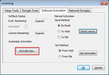
- If you have a dongle select the ”Download Latest Security File” button. Once done you will get the following message.
If you have a firewall or your Windows security blocks the replacement of the file you will have to first remove the existing one manually. To do this go to MENU | | HELP | WINDOWS EXPLORER. This should open Windows Explorer at the Caddie folder. Find a file called MSDBUTILS.DLL and delete it. Now try the Download Latest Security File“ again.
If dongle number is blank
If you have a Dongle and it is plugged in and lit, run the Uninstall Hasp Driver followed by a Reinstall Hasp Driver from the Hasp Tools Tab. Note the driver installed should be as shown or higher.
MAINTENANCE DATE IS REPORTED INCORRECTLY
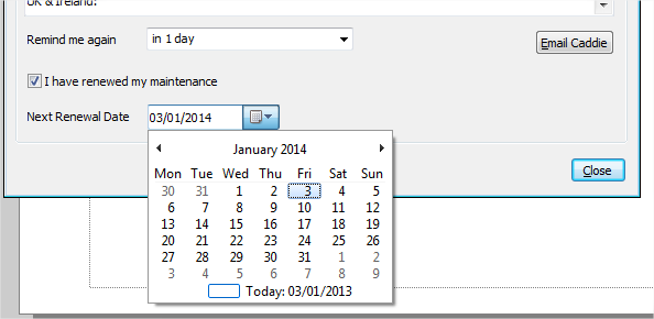
Caddie has an inbuilt notification of the maintenance date for the dongle currently plugged in. This date is normally set from the online database and in some cases may take some time to update. However if you wish you manually update the date for the dongle, go to HELP > MAINTENANCE INFO. If you don't know what your maintenance date is, contact Caddie support.
Tick the box “I have renewed my maintenance” and set to date to the correct date of maintenance expiry. If this is unknown, contact Advanced Computer Solutions for the date on record.
Note: If this is the first year of using Caddie then the date will usually be the initial invoice date. If you have already updated your maintenance an email would have been sent with the new expiry date. In some cases the invoice for any updates may include the expiry date.
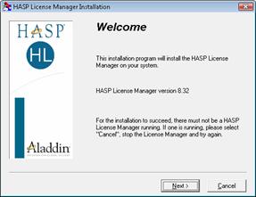
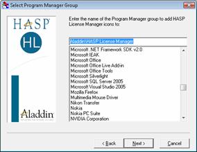
INSTALLING NETWORK DONGLES
Before installing the Network Dongle
On the Dongle Server:
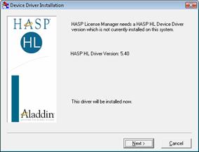
 |
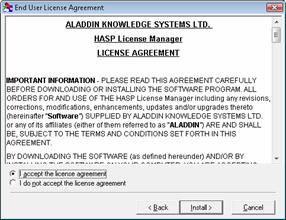 |
| Check the driver is 8.32 or higher. Select ’NEXT’ | Accept the licence and click ’INSTALL’ |
 |
 |
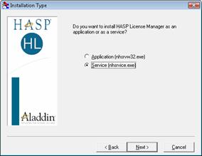
| You can install the Licence Manager as a service or load it at start up. It is preferably to load it as a Service. Select the required option and ’NEXT’ |
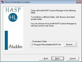
Use the default install path (you can change it if required). Select ’NEXT’ |
 |
 |
| Use the provided group name and ’NEXT’ | Select ’NEXT’ and the Licence Manager will be installed. |
| If you have a Network HASP plug into a spare USB socket and wait for it to light. If it doesn’t light reinstall the HASP driver from the Install menu on the CD or form ’CADDIE | HEPL | DONGLE INFO’ and the HASP TOOLS tab (see above). |
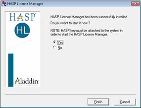 |
| Then select ’FINISH’ |
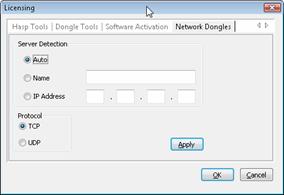
On the Caddie Workstations
After following the above procedure, the Network dongle should work.
Setting the Network Address
To Run Caddie on a Windows 7 computer the latest HASP Driver (dongle driver) is required.
This can be downloaded from the following link:
Note: to see the download button on the link you will need to log in.
To Install
- Download the file to the local computer (make a note where it is saved).
- Right Click on the downloaded file and select 'Send To', Select 'Desktop (create shortcut)' from the list that appears.
This will create a shortcut on the desktop. - Locate the shortcut and right click it then select Properties.
- In the 'Target' box add -r to the end of the line (Note this is a space followed by -r).
The target will now look something like:
C:\Downloads\haspdinst.exe -r (assuming the file was downloaded to 'c:\Downloads')
- Select OK to close the dialogue.
- Double click the shortcut - A small progress box should be displayed and after a few minutes it should read 'Operation Completed Successfully'.
- Click OK to close the progress box.
If User Account Control is set to a high level, you may have to confirm your permission for the program to run.
- Locate the shortcut again and right click and select Properties.
- In the 'Target' box, change the last character from r to i.
The target will now look something like:
C:\Downloads\haspdinst.exe -i (assuming the file was downloaded to 'c:\Downloads')
- Select OK to close the dialogue.
- Double click the shortcut - A small progress box should be displayed and after a few minutes it should read 'Operation Completed Successfully'.
- Click OK to close the progress box.
If User Account Control is set to a high level, you may have to confirm your permission for the program to run.
The hasp driver is now installed.
Note: You must have administrator permissions to perform the above task.
If for any reason any of the above tasks fail, then you should change the User Account Control (UAC) settings.
To do this type UAC in the Start menu search bar and choose "Change User Account Control". Change the slider to the lowest level.
Also set the Privilege level by right clicking the shortcut and from the Compatibility tab tick the 'Run as Administrator' tick box, and retry.
Caddie uses OpenGL graphics libraries, so graphics cards specifically designed for OpenGL such as nVidia's Quadro or RTX ranges and AMD's Radeon range will give the best performance.
On board graphics should be avoided as these are generally designed to be used with general office software and not CAD or 3D programmes such as Caddie. If your computer has only an on board graphics processor, purchasing and installing a standalone graphics card will often greatly improve the display capabilities of your computer.
Yes you can, on all versions of Caddie since Caddie 10. Copy the plotstyles into the plotstyles folder and Caddie will use them. To find out where the plotstyle folder is located, open Caddie then go to Settings -> Environment Settings and expand the Folders option.
Use the same technique if you get a plotstyle when you receive a drawing from a colleague that you are working with.
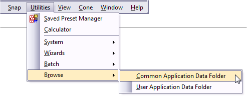
On Caddie 16 and later, you can get to the default plotstyles folder very easily by going to Utilitiess -> Browse -> Common Application Data Folder. In the list of folders you should see one called Plotstyles.
Applies To
All versions of Caddie from Version 15
Answer
Yes you can. Copy the .pat files into the hatch folder and Caddie will use them. To find out where the hatch folder is located, open Caddie then go to
MENU->SETTINGS ->ENVIRONMENT SETTINGS
and expand the Folders option.
Alternatively (if using the default folders) go to
MENU->UTILITIES->BROWSE->COMMON APPLICATION FOLDER
This will open Windows explorer. There you will see a folder named "HATCH". It is in this folder where the Custom Hatch patterns (*.PAT) are stored. Caddie will automatically pick these up when required.
Yes you can. Caddie can be installed on as many computers as you like.
- If you have a dongle, it must be plugged in to the computer and must remain in for the entire working session or Caddie will revert to demo mode and stop saving drawings.
- If you have a softlock, that can only reside on one computer, but can be moved between computers.
- If you have a cloud licence, the first computer to start Caddie will take the licence and will retain it until Caddie is closed.
If you want to use Caddie simultaneously on more than one computer you will need to purchase additional licences.
If you have several computers that you want to use Caddie on, the most convenient method is the cloud licence.
Note, that if you want to use a cloud licence without internet access, it can be detached and located on a particular computer for a designated time period, after which it will automatically be returned to the cloud. Should you wish to return it earlier, this can be done as long as you can get access to the internet.
General
When should a licence be moved from one machine to another?
A softlock should be moved from one machine to another when the user wants to use Caddie on a different machine permanently, or prior to a machine having a disk changed, formatted etc., after which it can be moved back if required
The process involves 3 stages:
· Obtaining the ID file for the destination machine
· Removing the licence from the source machine
· Applying the licence to the new machine
Obtaining the ID file for the destination machine
On the destination machine open a browser window and type in the address: http://localhost:1947
The Sentinel ACC (Admin Control Center) should open. If it doesn’t, reload the Caddie Hasp Drivers.
![]()
Select Diagnostics from the left menu
![]()
Click the Create ID File, as shown above. Save the file. This is the unique ID of the destination machine and is needed in the next stage.
Removing the licence from the source machine
Start the Caddie_Remote_Updater.exe program. On a standard installation it can be found in:
C:\Program Files\Caddie\Caddie xx\Tools\caddieinfo where xx is the version of Caddie
Select the ‘Transfer Licence’ Tab
![]()
At the bottom of the dialogue there are three options you must complete:
![]()
When you have completed the options, select ‘Generate Licence File’ and a file containing the licence will be created with a suffix of ‘h2h’ (host to host).
Applying the licence to the new machine
Copy the file created above to the destination machine. On the destination machine open a browser window and type in the address: http://localhost:1947. Select the ‘Update/Attach’ option from the left hand menu.
![]()
Use the browse button to browse to the h2h file you have just copied, select the file then click the ‘Apply File’ button. Check the text in the middle of the page to ensure the licence has been transferred successfully.
Notes:
1. If there are several licences on the source machine, check to see which licence Caddie is using prior to transferring it. To do this, close all active programs then start Caddie, then in a browser window type in the address: http://localhost:1947. With ‘Sentinel Keys’ selected in the left hand menu, look at the ‘Local’ licences and check which one has active sessions. Note the key ID on that row. This is the Key ID you want to transfer.
![]()
2. If you are using any version of Caddie prior to 24, you will also need the matching activation file for your dongle. Having transferred the licence, if Caddie starts in demo mode, from the top menu select Help -> Dongle Info
![]()
Choose the ‘Dongle Tools’ tab. Check that the dongle number shows correctly, then click the ‘Download latest licence file’ button and follow the prompts. This step is not required from Caddie 24 onwards.
If after creating 3D points from 2D points in the DTM commands the resultant points have a height of "0" we need to look at the text in more detail.
The text you see on the screen may be the result of some text formatting, and this does not show the added formatting in the text.
For instance the screen text may look like this 184.40 but if the text is edited (CSM>Edit Text) and the "Show format codes" tick box is ticked the you will now see any codes used for the displayed text. It may look like this - {\C256;184.98}. For the details of what the codes mean you can search the help from within Caddie for - Enter text, Text Format or Special Characters.
To remove the format of a single Mtext object, select the text on its own and from the CSM>Text>Remove format Codes.
This is great for a single paragraph of text however we are likely to need to do this for all the height text in the drawing.
To do this we need to first isolate the Mtext we need to change. This can be done in many ways and will depend on the current drawing. If this drawing has used layers for the Mtext then isolate the text by displaying only the layers. Now select all of the Mtext (if you have isolated the Mtext use Ctrl-A). From the CSM choose explode and exploded the Mtext. The text now is converted to MText. The 2D to 3D points command only works with Mtext, , so this has to be converted back. To do this select the command
Opening a Caddie drawing into other CAD programmes causes multiple objects to be selected when selecting a single object.
Background
In caddie we use a function called Patterns. This is function logically associates all the objects in the Pattern by assigning a unique name all the Patterns objects share. The objects in a pattern can be manipulated (copied, moved, rotated and have their properties changed etc.) either individually, or by using a Pattern command, all at the same time (like a group) without physically locking them together as Blocks would do. This functions is also used by other DWG based drawing systems but the function can have different names, typically “Groups”.
What happens with Patterns (Groups) when opening a DWG drawings in another programme
When opening a Caddie generate drawing in other programs the functionality of Patterns remains the same as it does in Caddie. However the default way in which these are handled in these other programs can be different. For instance some other programmes default to selecting all the objects in a group (pattern) when a single object is selected. To the untrained eye this gives the appearance that the objects are block when in fact they are not.
How to Change the way Patterns (groups) are handled in other DWG programmes
To change the way these groups (Patterns) are treated you may need to check with your software user guide to find what the control is to change the “Select All” function.
As an example you may find that you can toggle group selection on and off by using a keyboard shortcut such as CTRL+H or SHIFT+CTRL+A. Some systems also have settings in the options dialogue for selection. Look for something like “Selection of Object Grouping” or “ Object Grouping”. Also look in your products user guide for the System variable such as “PICKSTYLE”.
Searching the internet using your favourite search engine for “Object grouping DWG” or “DWG PICKSTYLE” will also turn up a number of useful tutorials and help pages.
How To Have a Single Click Selection of Patterns (Groups)
You might be interested to know that the single click selection is an option in Caddie. To set this up go to 'MENU | SETTINGS | MOUSE'. Selectio the 'PATTERN SELECTION' option from the left Single Click drop down.

Applies To:
Caddie 16 or later
Question:
I have a very large image I need to insert into a Caddie drawing. What is the best format to do this?
Answer:
When inserting very large images into Caddie the best image formats, are ECW and JPEG2000.
ECW is the format used for vary large terrain type maps, such as those from satellite images. Normally images of this type will already be in the ECW format. If you wish to convert an existing image to this format, you will need an external converting programme.
The other format is the JPEG2000 (or JP2) format. This is the recommended format for large images such as scans from an existing drawing in high resolution. For instance an A1 drawing scanned at 600dpi.
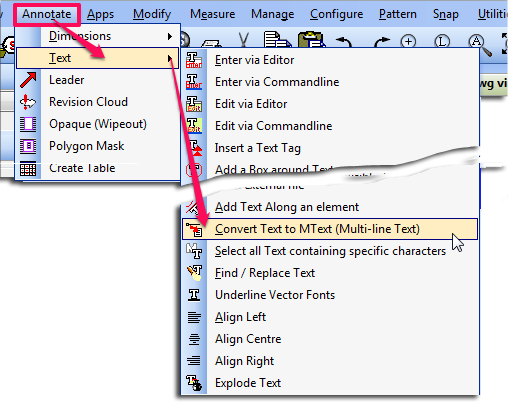
Modern scanners and output devices may be able to create these images in the JPEG2000 format. However if you are unable to create the JPEG2000 format, or you already have your image in another format, you can use the internal converter in Caddie.
This is accessed from Convert on the Modify Menu.

- Select Convert Image to JP2000
- From the explorer window select the file you wish to convert
- Select the folder where you want to save the image
A new image in the format of JPEG2000 with the existing name is now saved in the suggested folder.
The existing image is still intact.
Applies To:
Caddie 10 and later
Question:
I select some objects and I want to place them at a specific distance and direction relevant to where I pick the object from. I specify it using a X ,Y & Z co-ordinate but the object ends up in a completely different position. Why is this and how can I stop it happening?
Answer:
There are two ways in Caddie that the measurements are done.
ABSOLUTE (ABS) - the default in Caddie
![]()
Absolute will always make measurements from the UCS origin by default
So 0,0,0 will be the Zero Origin of the User Co-ordinate System (UCS). The UCS is on the World Co-Ordinate System (WCS) by default.
The UCS can be moved, so therefore the absolute position is also moved.
If when typing in the x,y,z co-ordinate value, it is preceded by a hash (#) - #0,0,0, the absolute measurement is made from the absolute position of the WCS.
RELATIVE (REL)
![]()
Relative measurements are always taken from the current origin in the drawing, which is indicated by a small white rectangle.
Conclusion:
The reason your selected objects where moved to a position which you were not expecting was probably due to the fact the ABS flag was set and not the REL flag.
Applies To:
All versions from caddie 10
Question:
Please explain how scale and units work in Caddie
Answer:
The Scale
There is only one fundamental you need to understand about scaling in Caddie.
In Caddie Everything is drawn at a scale of 1 unit = 1 unit (1:1)
This is: All objects drawn on the MODEL or the SHEET(s)
The Units
In Caddie a unitary name (Base Unit) or no value can be assigned as the units in a drawing. It is important to understand that changing the base units does not change the size of a drawing. So if a line is drawn 4 units long it would still be 4 units long even if the base units are change from inches to millimetres.
So Why Use a Base Unit Name?
The reality is you don't have to, and that is why many drawings from external sources don't have the base unit set. However if it is set Caddie can determine what to do with it.
This can be explained with a simple example of a table.A table was originally drawn by the author in inches (24” x 48”), however the unit name was not assigned. Therefore as far as Caddie is concerned the size is 24 x 48 units. If this drawing was brought into Caddie using “Insert Symbol” a number of things will change the way this will look in our drawing.
Let’s assume a drawing we are working on had had its base units set to millimetres, the default, and we want to insert the table as a symbol.
When inserting the symbol Caddie can automatically scale the symbol drawing to match the current drawing as long as both drawings have a base unit set.. However if no units have been assigned to the symbol drawing, Caddie won’t know how to scale the symbol and so will not change the size. In this case our imported symbol will therefore be 25.4 times too small. This would also be the case if the converse was true, as shown below.
|
Working Drawing |
Symbol |
Result Scaled (Y/N) |
|
N |
N |
N |
|
N |
Y |
N |
|
Y |
N |
N |
|
Y |
Y |
Y |
So what happens if the symbol, with specified units, is re-scaled? In this example the table would now be scaled by the scaling difference of inches and millimetres. (25.4 times) So our table would now be 610 x 1220 units (approx).
In exactly the same way as just mentioned, copying from one drawing to another via the clipboard, including Detail Copy, will also take in to account the base units used, and as long as they are specified in both drawings, scaling will automatically be carried out.
A good number of survey or map drawings will be drawn bases on a unit value of metres, but the author of the drawing may have not assigned a a base unit. When opening a drawing without an assigned base units, Caddie you will be warned that no units have been assigned.
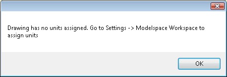
we could do as suggested, but the chance that we will also need to ere-scale the drawing
As already mentioned, changing the unitary value will not change the size of the drawing. If we require to take the metre drawing and change it to millimetres, we need to also rescale the drawing. In other words if the length of a line was drawn as 4 units we would need to scale it by 1000, so the line length is now 4000 units.
Because we need to change two things (scale and base units) a better way is to go to the Transformation commands in the Caddie Application and use the Rescale command.
This can be accessed from MENU-->MODIFY-->TRANSFORM-->RESCALE (Caddie 20 and later)
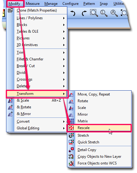
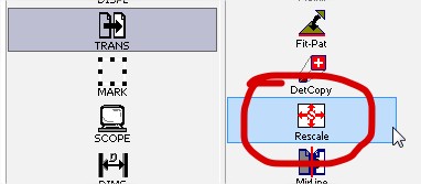
or from the Transform tools (Classic Menu)
This command does two jobs.
- Re-sizes the drawing
- Sets the Modelspace Units
Both are independent of each other, it is just convenient to do both at the same time.
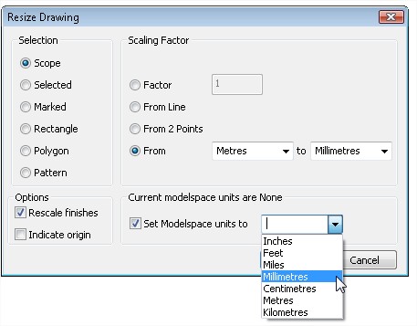
On the left of the dialogue choose the part of the drawing that we will apply the scale to. In the case of our map then this is likely to be the whole drawing (the Scope).
The Scaling Factor
This is where the scaling factor is either specified or measured.
Factor
Is a multiplication value
From line
You will be asked to indicate a line. The current length of the line will be stated and it can be amended with the correct value
From 2 Points
Similar to From Line. When there two points that can be measured, for instance the intersections of a grid
From
If the original target measuring unit is known this will take the ‘From’ and ‘To’ units to work out the scaling factor. Ensure you know that the drawing has been drawn in the selected units. If you are not sure use From Line or From 2 Points.
Options
Rescale Finishes
Here you can choose to scale or not scale Finishes (Text, Dimensions and Hatch etc).
Set Origin
If ticked you will be asked to indicate the new origin of the drawing. If unticked, the current origin will be used.
Modelspace units
The first line states what the current units are. If this is incorrect the change them here by selecting the required units and ticking the box.
When the values are correct, select OK.
Both the drawing and, if ticked, the base units will have changed. On completion it is unlikely that the drawing will be visible. Don't forget, in this case, the drawing is 1000 times bigger, and you are probably looking at a blank space in the drawing. If a Zoom Extents is done the drawing should show.
After scaling the drawing it is always worth doing a measure of the drawing,
If for some reason you need to re-due the scale, make sure you know what the current measurements are before scaling.
Final point
If you are using the drawing for insertion as a symbol or just bringing part of the drawing in via the clipboard, you don't have to re-scale the original drawing. All that is needed is to set the base units to the correct units of the drawing. For instance the map that is drawn in metres, set the base units to Metres. When copying via the clipboard Caddie will do the scaling for you. If you intend to use it as a symbol that save it after assigning the base unit.
Applies to:
Caddie 11 and later
Question:
If I accidentally drag my command bar or other toolbar from the docked position, is there a quick way to restore it?
Answer:
If you double click the top "Blue" bar of the tool bar it will revert to the last docked position.
If you to reset all the toolbars back to a previous saved setting, use 'Settings à Screen Layout à Recall Screen Layout' . If you haven't saved a screen layout then restore the "Original" layout, set it up again the way you like it and save the screen layout - just in case you need to do it again. Once saved it is wise to export it to an archive folder / drive.
The maximum number of active viewports is determined by the system variable: MAXACTVP
To increase the number of active viewports that will be visible on a sheet, go to Utilities->System->Set System Variable
Type MAXACTVP on the command line, then press enter. When prompted type the number of viewports you want to see, then press enter.
Applies To
All versions of Caddie from Version 10
Question
How can I save a drawiing in a different version of DWG?
Answer
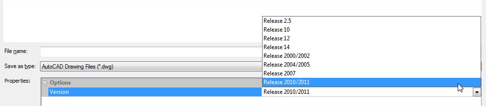
With the drawing open, go to MENU>FILE>SAVE AS or MENU>SAVE OTHER> SAVE COPY (Ctrl+F2)
In the dialogue that has opened, select the DWG version displayed, and a drop down list will display all the versions that can be saved. Choose the required one.
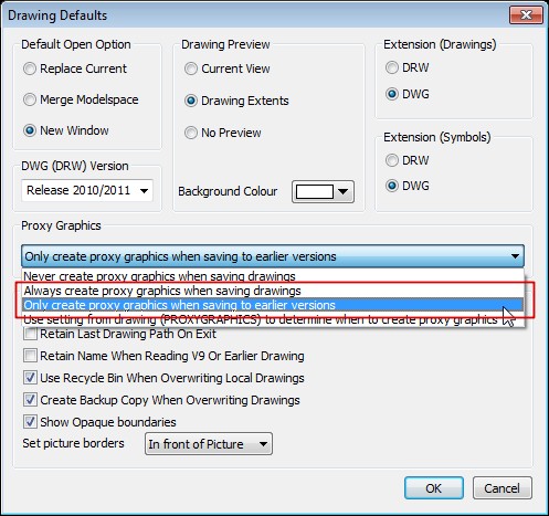
Note: if the drawing contains any AEC objects and is Caddie 17 or later (2010 / 2011), saving to earlier DWG versons will require saving the AEC objects as "Proxy Objects". This is true for Caddie users or other DWG users.
This is done in MENU>SETTINGS>DRAWING DEFAULTS.
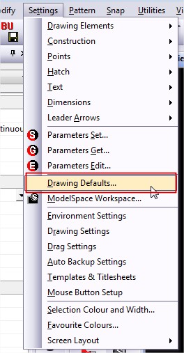
Select either of the two options shown in the box with the red line as shown below.
Applies To
All versions of Caddie from Version 12
Question
How can I email a drawing from caddie?
Answer
The method you use will depend which method you use to send emails (local client, such as Outlook, or web-mail). However if you use web-mail and want to send Zipped drawings read the Client Section.
I Have an Email Client
This command assumes that you are using an Email client such as Outlook, Outlook Express,
Windows Live Mail or any other third party email client.
Select Email Drawing... from the File Menu.
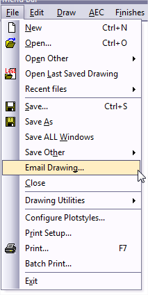
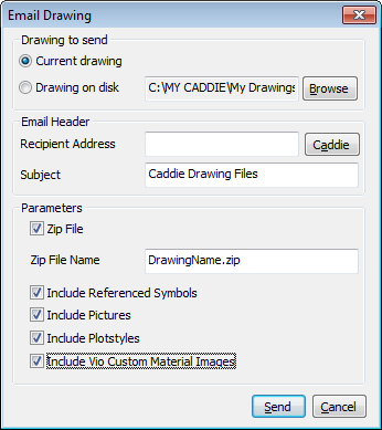
Set the parameters as required. If" "Zip File" is ticked you will also be able to attach any drawing used reference symbols, pictures, plotstyles and Vio materials.
As said this command assumes that you are using an Email client such as Outlook, Outlook Express,
Windows Live Mail or any other third party email client. If try to use this method without having a client installed you may get an error when trying to send a non-zipped drawing
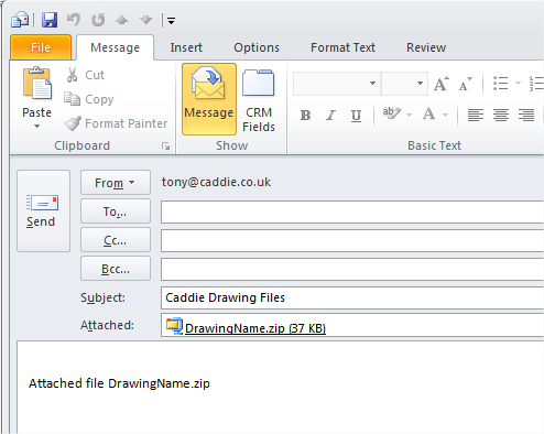
If you do have a client installed and "Send" is selected, Caddie triggers your email client to create a new message which has the drawing, or the zipped file (which includes the drawing and selected attachments such as images) attached.
You can specify the recipient in the Caddie Email dialogue, or if left blank enter it in the actual email. This is often easier as most email clients remember previously used email addresses and therefore save some typing.
I don't Have an Email Client, I use Web Mail
Sending and email using Caddie email only works with an email client. With Web mail you first have to run your browser and log-on to your web-mail site.
However you can still add a drawing or send a zip file as an attachment.
To add a drawing just use your web mail to create (compose) an email and select the attachment (usually an icon in the shape of a paper clip). Now just point to the file or files that you want to attach. If you want to send a zipped file you will first need to create it using a programme like Winzip or Winrar (there are many more available on the web).
Alternatively you could use Caddie to create the zip file.
What is little known is that when emailing a drawing, within Caddie, if the ZIP box is ticked, a copy of the zipped drawing is saved in a temporary folder and it is this file you can use.
To find this file in Caddie 17, go to
MENU>UTILITIES>BROWSE>USER APPLICATION FOLDERS
and look for a folder called tempemail$$$
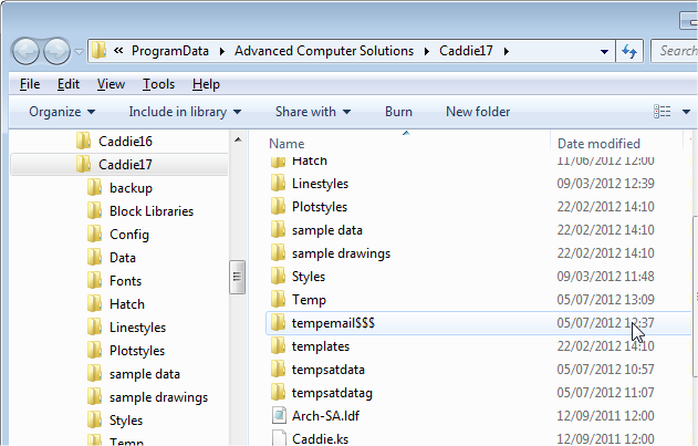
In this folder you will find a zip file with the drawing name. Attach this to you web-mail using your normal web-mail attachment link.
Version
Caddie 15 onwards
Question
I have a requirement to show Feet and Inches in addition to the current metric dimension. How do I do this?
Answer
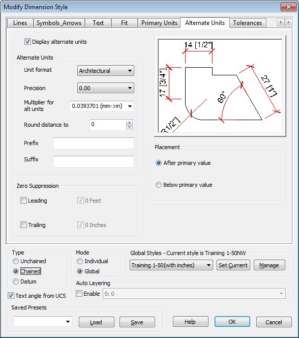
In Dimension Set go to the Alternative Units tab
Tick "Display Alternate Units"
Set the Unit format to Architectural
Set the Precision to 0.00 making this 0.000 will show 1/8" values
Set the Multiplier to mm>inches
Click OK and start using.
The alternative values will be in Feet and Inches
NOTE
If you are using styles first make a new style based on the one you want to change. and edit the new one. Don't forget to make the new one the current style
Requires
All versions of Caddie* (The context menu option is from Caddie 17 Build 3)
Question
Can I save and recall a zoomed view.
Answer
Yes this is done using the Store Zoom and Recall Zoom commands found in the Display section of the Caddie App or from Version 17 build 3 on the context sensitive menu.
With larger drawings, 3D drawings and AEC drawings getting the view on the screen as you previously had set can be time consuming. Using the Save and Recall views commands can save a lot of time, and take you straight to any orthogonal or perspective views you may be using,
Saving / Recalling
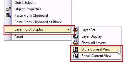
To save a view for future recall, use the standard Caddie Display – Store group of commands. For ease of access the store view and Recall View buttons are also on the Context menu under Layers & Display
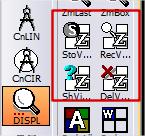
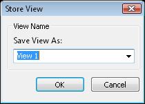
StoView
- Presents a dialogue where you can give the current view a name. This will also remember if the view is perspective or non-perspective
RecView
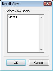
- Available from the Context Menu under Layers and Display. See Above
- Recalls any previously stored view
- Select the required view from the list and the OK.
Show View position
- Only show views created on the WCS – in other words, as viewed for a 2D drawing, so not of interest here
- Delete View
- Deletes either the indicated or all stores views
Applies To:
Caddie 16 and later
Question:
I realise that if my company logo is simple then creating the logo as lines, polylines etc. and hatch is the best way. However there are subtle shades of colour in my logo and it would look best as an image. In a .dwg drawing images are attachments to the drawing. This means that when I send the drawing to someone I have to make sure the images also go.
Is there a way where the image can be embeded in the drawing?
Answer:
Images can be embedded in the drawing, but this method is best kept for very small images such as logos.
To do this use any Windows program that will show the logo on the screen. You can use the Preview function of Windows Explorer, Internet Browser if that is where you image is or a dedicated image editor. The important thing is to see the image on the screen.
Make the display of your logo about twice the size of the final display size of the logo. So if the logo is 50mm wide make the display of the image 100mm wide. Some programs allow the mouse wheel or Ctrl+mouse wheel to zoom in/out
Now you need to capture this.
In Windows Vista or Windows 7 there is a capture tool in "All Programs" "Accessories" called "Snipping Tool". or you can can use your favorite screen capture tool to do this.
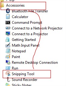
Using the snipping tool select NEW and RECTANGLE. Now tightly select the logo.
Now we have captured it we to get it into Caddie.
Go to the Sheet where the logo is to be placed. From the Menu select "Draw | Advance Object | Insert OLE Object and the "From Clip Board".
Indicate the bottom left position of the logo. It will look too big so select it and right-click-scale. Dynamic scaling works the best. Select the lower left corner and then the lower right corner and drag this corner until the image is the right size. If this is going to be used a number of times make it into a block. and then insert it as a block reference.
The Sheet will show a border, but this doesn't print.
![]()
Note:
Inserting images this way is useful but scaling visual size doesn't change the embedded image size. The size of the embedded image will be the size of the capture, so keep the capture size as small as needed. every image inserted in the drawing will increase the drawing size.
Applies to
Caddie 12 and higher
Question
Why do my leaders (or other objects) show on screen but not plot?
Answer
There are a number of reasons why they may not plot - here are some common ones:
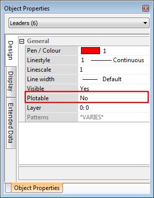
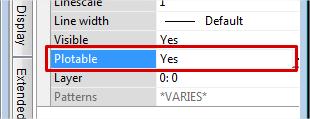
1. The General | Plotable is set to NO.
This can be change to YES in the Object Properties dialogue, by first selecting the leader(s) that need changing and changing the parameter to YES
To Change all –
- Use “QUICK SELECT” from the context menu
- Select Scope | Leaders | Plotable |= | No
- SELECT
- CLOSE
- Use Object Properties
- Change Plotable to YES
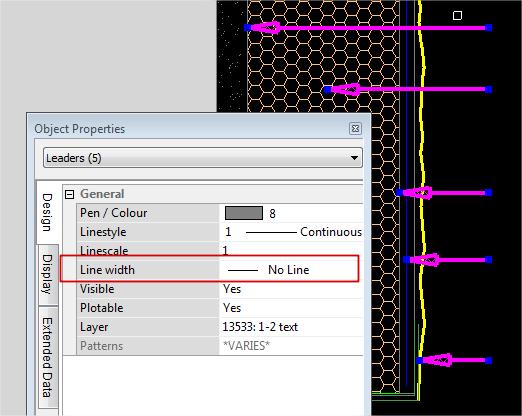
2. The line thickness is set to 0.0 (NONE) as shown below.
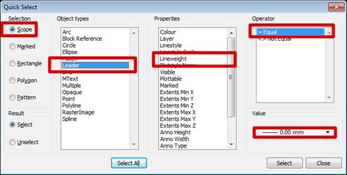
To Change all –
- Use “QUICK SELECT” from the context menu
- Select Scope | Leaders | Thickness |= | 0.00
- SELECT
- CLOSE
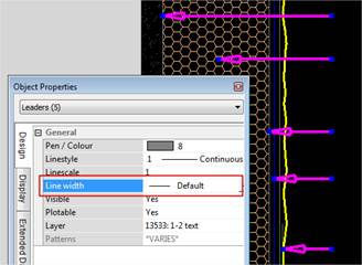
- Use Object Properties
- Changed to a thickness of default
Applies to:
Caddie 16 and later
Question:
How can tables be created user-definable rows and columns?
Answer:
To create a new table, from the dropdown menus at the top of the Caddie screen select Draw -> Advanced Objects -> Create Table
To edit an existing table, from the dropdown menus at the top of the Caddie screen select Modify -> Advanced Objects and select the required command, or from Caddie 17 onwards just select the table and then choose the editing command from the context sensitive menu.
Applies to:
Caddie 17 Build 3 and later
Question:
I have a drawing and it contains many symbols that are created using a lot of lines and arcs. Is there an easy way to convert these lines and arcs to polylines to make the drawing smaller and more manageable?
Answer:
Select the set of lines and arcs that you want to convert, then from the context sensitive menu select Make -> Polyline from Lines and Arcs
Caddie will replace the lines and arcs with polylines. If you want more control over the conversion, then you can use the Modify Mk->Poly command.
Applies to:
Caddie 16 and later
Question:
Why do my DTM sections appear as straight lines when I know the section is not level
Answer:
The most common reason for this is not using consistent units between horizontal and vertical dimensions. For example if all your spot heights are in metres but you scale the survey so that horizontally it is in millimetres then the horizontal scale will be 1000 times the vertical scale. Luckily Caddie has a vertical scaling factor for sections to allow for this. If your horizontal scale is in millimetres but your spot heights are im metres, just set the vertical scaling to 1000 and the sections will look correct.
Applies To:
Caddie 16 upwards
Question:
My insulation lines look great on screen, but when I plot them they are massively oversized. How do I fix this?
Answer:
For each sheet there is an option of whether to scale vector linestyles. If the insulation or car parking, or in fact any of the vector linestyles appear far too big, then ensure that you are in the sheet you want to change then go to Sheets -> SetSht and on the bottom right of the dialogue change the checkbox called 'Scale Viewport Linestyles'.
Why is the option there?
If you have several different viewports at different scales and you want the linestyles to look the same size in each (for example for a linestyle such as Center) then the checkbox needs to be switched off. However in the case of insulation linestyles etc., where they should be drawn according to the scale, scaling should be switched on.
Applies To:
Caddie 12 upwards
Question:
I have opened a drawing from another DWG user and there are lots of Reference Symbols in the drawing. I want to embed these references in the drawing so they become part of the drawing. How can this be done retaining the original grouping?
Answer:
The easy answer is to explode the references. What this does is to replace the Reference symbol with real objects which the reference was displaying. The problem doing this is, if the symbol hadn't used patterns (DWG groups) there would not be any relationship between the objects and it would therefore be difficult to select all the objects now created.
What would be better in cases like this would be to replace the Referenced Syymbol with a Block. A Block Reference works in a similar way to a Reference Symbol, in that it shows a representation of the original objects. Where it differes is where the referenced objects are stored. In the case of a Reference Symbol the object are in another file, in a specified computer location. This means the Referenced Symbol has to be aslso sent to a new location (on other computer for instance).
Block however reference object already in the drawing
We do a lot of structural steelwork which involves drawing many nuts and bolts. Whilst we can use blocks and symbols etc. can't Caddie automate the process for us?
Yes Caddie can. The Mech application has a couple of tools for drawing hex head, socket cap and socket countersunk bolts and also nuts, washers etc.
Applies to:
Caddie 16 onwards.
Note: From Caddie 17 onwards the bolt command is further automated to add automatic size parameters and optional nuts.
Whilst it is very easy to select all objects inside a rectangle by simply ending all commands then indicating two points, can I easily select all points outside that rectangle?
There are a whole suite of tools that can be used to either select or mark objects and one of these does exactly what you are asking for.
From the Caddie Application main toolbar on the left hand side of the screen, choose the 'Select' command. If there is no 'Select' command hold down the Tab key and choose the 'Mark' command, which will change to say 'Select'
From within the selection commands, choose the MSRect command and then from the dialogue choose 'Elements Outside'. When you indicate two diagonals of a rectangle, Caddie will now select all objects outside the chosen rectangle.
Applies to:
Caddie 16 onwards.
Applies To
Caddie 15 onwards
Question
My drawing is done in mm but I need to measure some dimensions in inches. Can Caddie do this for me?
Answer
Yes, Caddie has a feature called 'Alternate units' for measuring. From the Measure menu on the left hand toolbar, select AltUnit. Choose your Drawing Units (mm) and Measurement Units (Inches) and tick the 'Show Alternative Units' tickbox, then when you measure something, Caddie will show the alternate units in bracxkets after the normal dimensions.
An example might be: Diagonal distance = 18381.2 mm (723.669 inches)
Applies To
Caddie 25 onwards
Question
How can I convert a .IFC file to .DWG?
Answer
In Caddie Professional, from the top menu select File -> Open and change the File Type to Bin Files (.IFC).
Browse to the file, select it, open it then from the top menu choose File -> Save As to save the file as a .DWG file.
Applies To
Caddie 15 onwards
Question
We have a drawing from somebody with lots of viewports on the sheet. In the modelspace there are many similar parts to the drawing. How can we easily see which parts of the drawing the viewports refer to?
Answer
From the sheets menu on the left hand toolbar select the ShowVP command. Caddie will change to the modelspace and draw virtual boxes around the areas that the viewports refer to.
Note that only orthogonal viewports will be shown in the modelspace.
Applies To
All versions of Caddie from Version 10
Question
I change the pen or line style of a Block Reference, but nothing seems to change.
Answer
Firstly the properties that you are changing are those of the Block Reference itself. A Block Reference is an object in its own right. What you see displayed is the content of an indicated block table, which is in a hidden part of the drawing. Think of a Block Reference as a snap-shot of the block information. Therefore to change the property of the contents of a Block Reference you need to change the objects displayed directly.
As Block References are only snap-shots, changing the properties of the contents will affect all Block References with the same name.
So how do we change the pen of objects displayed in Block Reference? This will depend on how the pen for the object is specified and what the result should be. Firstly we need to determine what pen is being used. To do that we need to edit a block. By selecting a current block and with a right click (Context Menu) select EDIT. You can now do an object properties to find the object's properties. Don’t forget to end the block editing when finished (CONTEXT | ABORT | CONTEXT END EDIT BLOCK).
Most surveys specify the pens “By Layer” so as long as it is all the objects in a particular pen that need changing, the quick solution is to modify the layer assignment to the required pen. To do this, select the Layer Set dialogue fron CADDIE | SCOPE | LAY SET and change the layer asignments as required. This way, there is no block editing to be done, however if the lines need to be assigned to a new pen directly, then each block will have to be edited.
To do this we need to edit a block. You can either select a current Block Reference or the preferred method is to insert a new occurrence of the reference, (MENU | FILE | INSERT OTHER | BLOCK REFERENCE selecting the required reference) into the drawing and right click (Context Menu) and select EDIT. Select and change with object properties the objects to be changed. Don’t forget to end the block editing when finished (CONTEXT | ABORT | CONTEXT END EDIT BLOCK). Also if a temporay occurance of the Block reference has been used, don't forget to delete it as it is no longer required.
You may have noticed that not only can we have a direct pen assignment and BY LAYER, but one of the pen assignments can also be BY BLOCK. If that is the case, the objects assigned with this property will automatically take on the properties of the Block Reference, so the only editing that needs to be done is to the Block Reference itself.
The above applies to all object properties, including Line styles and Layers etc.
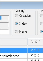
Question:
There are a number of places where there is a drop down for layer selection. How can the order of the displayed layers be changed.
Answer:
Changing the order of the layers in the dropdown selectors are all done by right clicking the layer box. As there are slight differences each is described separately.
The Layer Selector on the Standard Tool Bar
To change the layer order on this tool bar first select the black dropdown triangle. This expands the layer list.
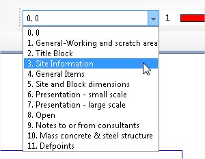
Right click anywhere in the expanded list and you will see the order selection window.
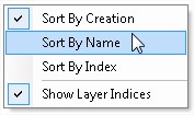
Select the method you require.
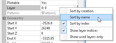
The Object Properties Layer Selector
One of the properties of any objects is the layer. Selecting the dropdown triangle displays a list of available layers. The order of these layers can be changed by right clicking in the current layer bar, not in the dropdown list.. Choose the required order from the list.
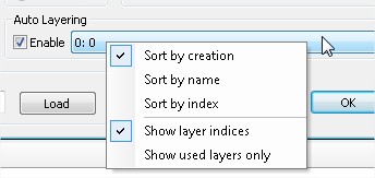
Auto Layering Selector
The last method is also used for any dialogues that have the Auto Layering selector.
Here the Dimensions Set Dialogue is shown. Other dialogues include, Text Set, Hatch Set, Walls Set etc.
Layer Set Dialogue
Finally the Layer Set dialogue (SCOPE | LAYERSET) has a number of radial buttons which can change the order.
Question
How is the display of the grid controlled?
Answer:
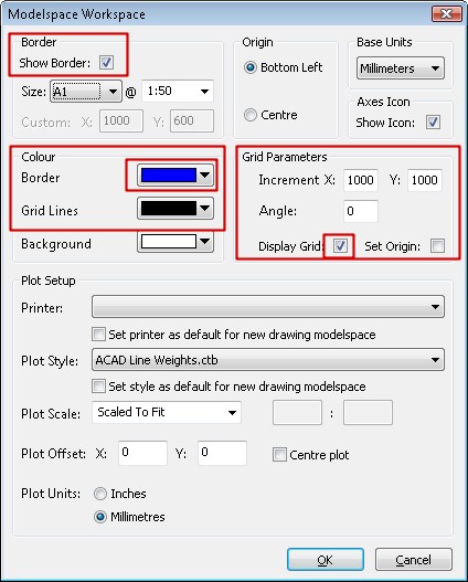
Grid display is determined by a number of factors. The grid display and grid colours are controlled from the ModelSpace Setup in Settings.
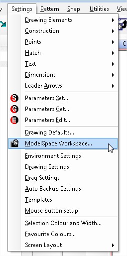
To display the grid both the Show Border and Display Grid tick boxes need to be ticked.
Earlier version of Caddie allowed the colour of the border and the grid to be displayed independently. That is no longer the case. Grid colours are changed using the border colour dropdown. The Grid Line Colour dropdown no longer has any use.
Grid Parameters allows the size and angle of the grid to be changed. The value of the X and Y dimensions is drawing units and will therefore be related to the current Base Units (which can also be set here).
If the Set Origin box is ticked, you will be asked for a new grid origin on exit of the dialogue. This origin is only the grid and is not either the WCS origin (which is fixed) or the UCS origin which is set by the UCS commands. This does , however effect the positioning of any grid snaps when used.
While on the subject of Grid Snaps, just remember that if the grid snap is ON the Grid Snap Icon on the status Bar will be set to Green.
![]()
When OF it will be the default GREY.
![]()
Notes:
- When ON the grid snap will take priority over other snap
- When the grid snap finds a grid intersection a rectangular marker will be displayed
- The grid does not have to be displayed in order for the grid snap to work
- The grid is only displayed within the current border area but is available over the entire drawing on the current UCS
- The origin of the border is placed on the current origin of the UCS
- The border and hence the grid is place on the UCS
- Once set, using the ModelSpace Setup dialogue, the grid can be turned ON or OFF from MENU | SNAP | TOGGLE GRID ON / OFF. To save time create a keyboard shortcut ('G' in not current ly being used)
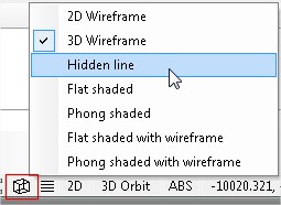
- The grid is displayed as a series of DOTS when the render mode is set to 2D WIREFRAME
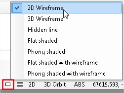
- The grid is displayed as a wire grid in all other modes (3D render mode)
- The current settings are saved with the drawing (which could be your template)
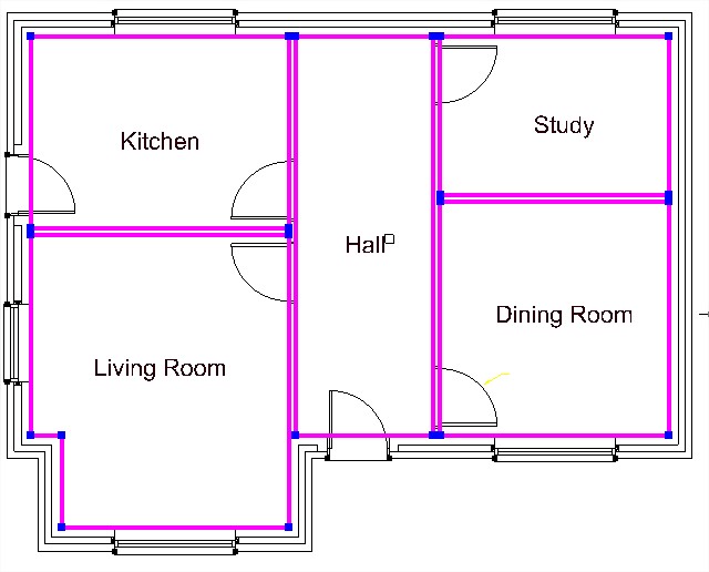
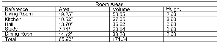
Question
In my drawing I have a number of rooms that I am required to provide area measurements of. I may also require to provide volume measurements. How can this be done in Caddie?
Answer:
There are a number of tools within Caddie that can make area measurements.
From Caddie 15 a new set of tools were added which makes area and volume measurement not only easy to use but also allows dynamic changes based on the drawing its self. I addition the information is presented in tabular form.
This set of tools can be accessed from one of the regional 2D architectural applications.
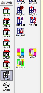
Those who use the SA Arch tools can find the measurement tools in the 'Sched' section.
Those using the ArchUK application can also find a 'Sched' section.
 D1
D1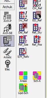
Which ever one you choose the process and results are the same.
You are first asked to draw around the area using a polyline. All the normal polyline modifications are allowed, such as curves and the close command.
TIP
If the area is a rectangle just indicate the two diagonal points followed by an 'Option End' and Caddie will do the rest. Remember this tip, as it can used in many other places where the only option is to draw with a polygon or polyline, and you want a rectangle.
When you do an Option End after each indicated area, the following dialogue will open
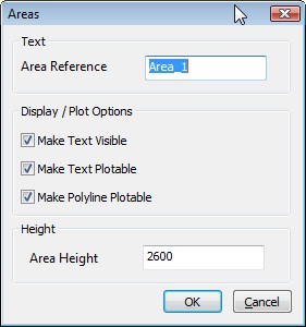
The 'Area Reference' is the room name etc. When the area is selected with the previous step a polyline is drawn.
The area reference text is placed in the drawing. This can be visible and / or plotable by ticking the relevant tick box.
The style the text uses is the current style as set in 'CADDIE | TEXT | TEXTSET' .
As this is standard text it can be edited and repositioned just like any other text.
If the "Make Polyline Plotable" tick box is ticked the polyline will plot.
If you require a volume also specify the height.
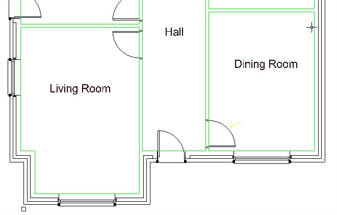
below is a typical selection 9the polylines are shown selected for clarity).
The room name were those specified in the dialogue above.
Once all the areas have been added, select the SCH-A tool and the following dialogue will appear.
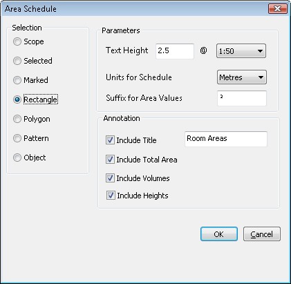
Choose the selection area.
Set the Text height and scale value.
The Units are the units of the table areas and volumes.
Add a suffix to the value if required. Leave blank for none. Note a number of fonts may give none or different characters than the one selected. Choose a font in the TEXTSET dialogue, which contains the character you want to use. If necessary use the Windows "Character Map" tool form Windows Start | All Programs | Accessories | System Tools.
The tick boxes allow the selection of the column titles. If "Include Title" is ticked, give the table a name.
When completed select OK and indicate where the table is to be placed.
The result will look something like this.
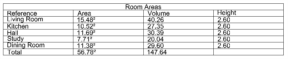
If some changes are made to the area, such as a stretch by 1000mm in this example, all that needs to be done is to use the UPD-Sch command
Indicate which table you want to update, and the changed values will automatically be updated.
{JFBCLike}
Applies To:
Caddie Version 11 and later
Question:
What are the different ways a co-ordinate can be specified.
Answer:
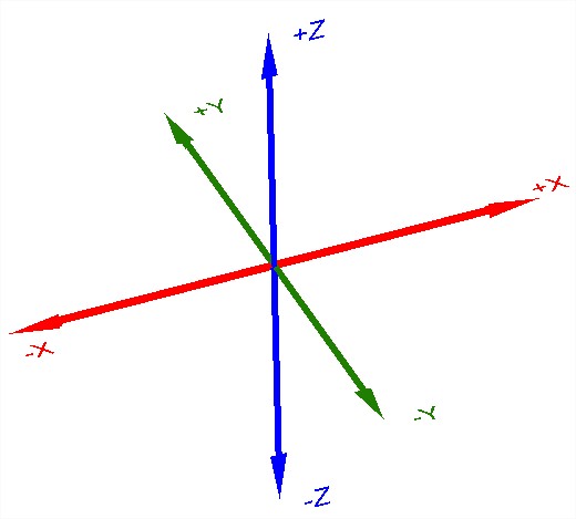
Understanding the coordinate system in Caddie
The coordinate system is based on three directions, “X”, “Y” & “Z”. The point the three axis cross is zero and is known as the origin. Assuming a top view, the “X” axis travels horizontally, the “Y” axis vertically and the “Z” axis perpendicular to the screen.
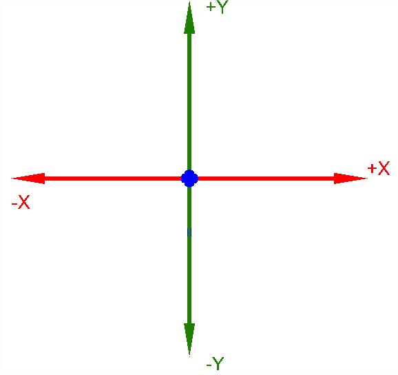
Looking at X in the figure above, the point of intersection is zero, distances to the right are positive and distances to the left are negative.
The position in the drawing where values are calculated from can depend on the setting of the 2D /3D and the mode flag we are using.
2D v 3D
Setting the 2D flag to 2D will override all height information and set the height to zero on the current UCS. Setting to 3D will take in to account any Z height values
Absolute v Relative
If we are using an absolute system (ABS on the status bar) the value will be bases on the current User Coordinate System (USC) origin.
![]()
When REL (relative) is set on the status bar, all coordinate measurements will be calculated from the current origin in the drawing (usually the last position selected).
![]()
Entering coordinate values in Caddie
Specifying Position (UCS)
The principle way is to specify the X, Y & Z values. This is entered in the form of
X,Y,Z
Caddie requires the first two values to be specified (X & Y) and an optional Z value. The Z value can be omitted if the value is zero.
If REL is set the Z value will be ignored and the height set to zero on the current UCS.
Specifying Position (WCS )
If the x,y,z value is prefixed with a hash (#) the values will be measure using the World Coordinate System (WCS) as the reference.
#X,Y,Z
If REL is set the z value will be ignored and the height set to zero on the current UCS.
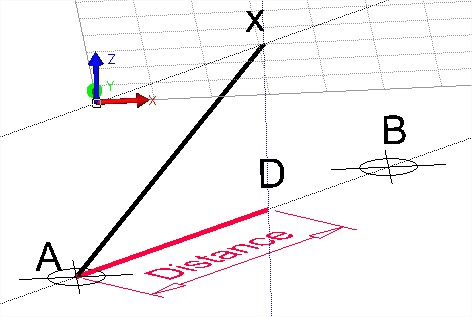
Specifying a Single value
If a single value is specified followed by a return, the value will only be the distance . The direction will be dependent on the current position of the cursor. If a snap is indicated, this snap point will be used for the end direction.
The 2D / 3D flag will have an effect on the length of the line.
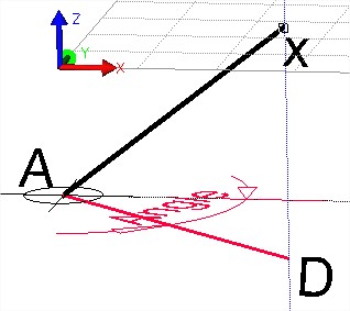
Look at the illustration below. The UCS original position is at the height of the two construction points and the lower construction line. With the 2D / 3D flag set to 3D a line was started at the construction point A. Setting the flag to 2D the second position was specified with only the distance and the snap set to the construction point B. What has happened is the distance has been correctly used (Point D) but the line has been drawn on the offset UCS (x). The vertical (blue) construction line clearly show that the second point is vertically above the specified distance from point A.
Specifying a Distance and Angular Direction (UCS)
To enter a distance and angular direction use the form
distance 3000<-30 will give a value from the current origin of 3000 with an angle of -30 degrees. This is based on the UCS.
The 2D / 3D flag will have an effect on the length of the line but not on the angle. Look at the illustration below. The UCS original position is at the height of the two construction points. With the 2D / 3D flag set to 3D a line was started at the construction point A. Setting the flag to 2D the second position was specified with only the distance and angle (distance
Specifying Using the Keyboard Arrow keys (UCS)
On the keyboard there are four Arrow keys. Up, Down, Left and Right. Entering a single value followed by one of those four keys, will set the next origin at the distance specified and in the orthogonal direction (UCS) indicated by the key pressed.
The 2D / 3D flag will have an effect on the length of the line. In a similar way to the two illustrations above. A line is started, with the 3D flag set and the first point indicated somewhere other than on the UCS. With the UCS offset and the 2D flag set the point is specified with a value and a cursor key on the keyboard. The line will be attempted to be drawn with the distance and direction stated. However because the UCS has been offset and the 2D flag is set, the end of the line will be on the UCS vertically above the apparent end point.
Applies To:
Caddie 15 and later
Question:
How do I do calculations in dialogue box fields?
Answer:
Depending on the complexity of the calculation and the input field type you can type it straight into the dialogue box field or alternatively you can use Caddie's inbuilt calculator to do more complex calculations.
If the field is a simple numeric input box you can type in a calculation and then either hit F2 or Enter to see the result.
Examples:
34+56
34 * 29
2 * 6 / 23
15 * cos(30)
For more involved calculations, or if the uinput box is a dropdown list, access the calculator by right clicking the field and selecting 'Calculator' from the dropdown menu.
Note:
When you right click on a dialogue input box you will often see 'Buffer' on the dropdown list. This is also available on many dropdown list boxes too, but on these you must right click on the small downward pointing triangle to the right of the list box.
Applies To:
Caddie 15 and later
Question:
I have created some custom toolbars, What would be nice would be to divide the tool bar up into groups of tools. how can I do this?
Answer:
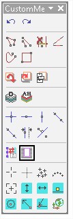
First edit a custom tool bar by right clicking any of the tool bars and selecting "Customize".
Icons on the tool bar can be removed, simply by dragging them off the tool bars, or reordering by dragging to a new position.
There are two methods to do this.
METHOD 1
Using the mouse.
Offseting icons slightly to the right forces the insertion of a group separator bar.
![]()
To do this grab an icon, to the right of the position where you want to insert a group bar, and move it about half an icon position to the right.
![]()
If you see an "I" bar then you have gone too far, so move a little to the left until the "I" bar disappears.
![]()
If you see figure 1 then you can let go and a group bar will be present on your tool bar.
![]()
If the tool bar is "floating" the group bar will extend the full width as shown in the example below.
Removing a Group Bar
To remove a group bar just select (whist in customize mode) the icon to the right of the bar and move it a half icon to the left.
METHOD 2
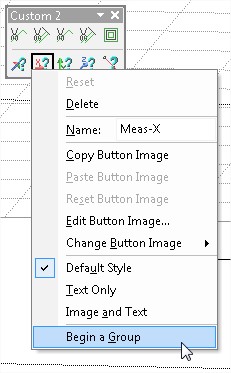
Using the context menu.
Enter the "customize" mode as above.
Right click on a command icon, which will be the foirst in the new group, and select Begin Group from the menu.
This will automatically add a group bar in the toolbar, just before the selected command icon.
Removing a Group Bar
Right click the first icon in the group and un-tick the Begin Group option.
Applies to
Caddie 15 and later
Question
What are Text Styles and how do they work.
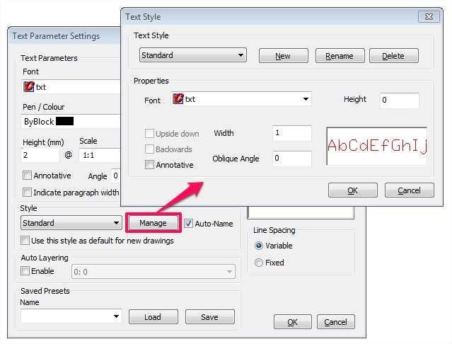
Answer
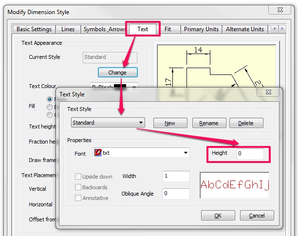
In Caddie all text has a style. A new blank drawing (created without a template) will have one style. The default Text Style is “STANDARD”. Accessing the settings for the style can be either from the Text Set dialogue (see below) or from the Dimension dialogue (see the end of the article)
|
Field |
Default Value |
Description |
|
Style Name |
STANDARD |
The name given to the style. The maximum length is 255 characters. |
|
Font |
TXT.shx |
Can be Vector (SHX) or True Type (TTF) |
|
Height |
0 |
The height of the text. Values >0 will override any individual heights set by ‘TextSet’. Normally set to 0 |
|
Width Factor |
1 |
1 is the designed width of the font. Values 1 expand the text. |
|
Oblique Angle |
0 |
The skew of individual characters. |
NEW styles can be created and the settings will be based on the default settings as shown above.
DELETE styles will delete only unused styles.
RENAME styles allows the renaming of any used styles.
Where Are Styles Stored?
Styles are a part of the drawing. Sending a drawing from one DWG user to another will also take the styles.
In the same way Text Styles can be within a template, making them available for any drawing that uses the template.
How Do I Get Existing Styles Into a Drawing?
Styles can be copied from one drawing to another by
- Copying any text with that uses the style to the clipboard and pasting into another open drawing
- Saving text with the style as a symbol and inserting a symbol into another drawing
- Using the component manager
Note: If a text style name already exists in the drawing the one in the drawing will be used and not the imported one. To avoid this rename the style in either drawing before combining them.
Using Text Styles
You can select the text style from the TextSet dialogue. In the same dialogue you can also make the current style the default.
When entering text from the Text Editor (EntEntr) you can choose the style from the Style dropdown.
How to ensure you have the same styles available for all your new drawings.
Using a template can be a great way to ensure you always start a drawing with the settings you prefer to use. Text styles saved in the template will be available for all drawings using the template.
Note
As mentioned above, the size of the text will depend on the size set or the OVERRIDE size, see the table above.
Text Styles are use by Dimensions
Dimensions also uses Text Styles to display the the text element. The text style may also be used for general MText. If the style is change in the Text-->Manage Styles, any dimension using the text style will also change. For a given dimension style both the text style used or the parameters of the text style can be changed using the settings in the dimension settings dialogue (see below). Again if the size of the text has an override, the dimension text size will be fixed at that size.
Applies to
Caddie 14 and later
Question
How can I import co-ordinate values from a text or Excel file.
Answer
Within the Survey Application there is a command specifically designed to import data from a text or excel file.
To access the survey commands the Survey Application ('Surv') needs to be loaded. If this haven't been loaded, right click on and application name (such as Caddie or 3D etc) and select Survey from the list. If you can 't see it is the list , it has already been loaded.
Before importing the data a few points need to be understood. Firstly the model units will need to be changed to the units used in the data file. So for instance if the data was specified in metres, the model units will need to match. Also any text that will be added, such as point names, will be placed at the current settings of text (from TextSet). So again if the units are to be metres, ensure the text is also set to metres (2mm = 0.002M). The font used will also be the font used by the insert data dialogue.
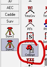
Select the Sur=2 group
Select 'CrdImpt'
When this command is run for the first time, you will be taken to the survey mode setup. You can also set this up at any time by using the 'Sur=1' command 'SrvMde'
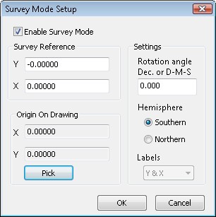
The origin on the drawing is the position that the imported measurement will be made from. if you use the default, the position will be the origin of the drawing (0,0). To chose another position, use the PICK button and select the required drawing position. To set it back to 0,0, use PICK and typ 0,0 (in ABS) as the value.
Choosing the hemisphere will determine the direction of the imported measurements. If in the northan hemisphere, also choose whether to use Eastings & Northings (E&N) or Y&X lables.
Once you are happy with thes settings, select OK and you will aksed which file to use for the data. This would normally be a TXT file but excel files can also be used.
Once selected the dialogue opens where you can set out the way the data should be used.
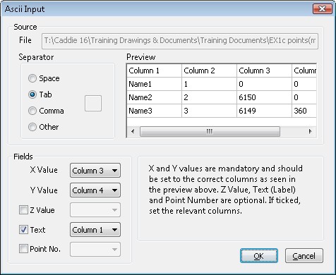
Change the settings as required and select OK. Contruction point will be place in the drawing, at the origin originally specified in the Survey Setup, which can be snaped to, to draw lines etc.
Applies To
Caddie 15 and later (some commands will be found in earlier versions)
Question
I can see that Caddie displays the order of objects in different ways. How is this done and can I change the display order.
Answer
Caddie has a number of display options available. These are accessed either from
'3D | 3D DISPLAY | R-MODE'
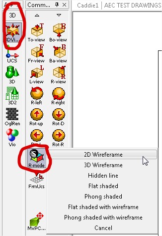
or from the status bar.
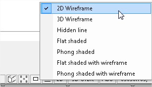
2D Wireframe is the only 2D rendering mode and displays objects in a different way to all the other, 3D, modes. The 2D wireframe rendering mode is the main subject of this artical.
2D Wireframe
In this mode every object drawn in Caddie will be drawn on its own display plane. In Caddie all new objects will be drawn on the top most display plane, that is the nearest to the viewer. So if a line is drawn followed by some text, the text will appear to be on top on the line.
The display order may not suit the way you want objects to appear. In the case of hatch, usually you would want to show the hatch behind any lines used to create the hatch path. For hatch only there is a way to override the default front plane positioning by going to the HATCH SET dialogue, where you will see the opportunity to set hatch to the back plane.
The hatch commands also include a set of commands where existing hatches can be moved to the front, the back, in front of an object, or behind an object. More details of these can be found in Caddie help.
![]()
All other obects will be drawn on a new front plane. You can rearrange these with a similar set of commands found in 'CADDIE | EDIT'. These commands will do, what we did for hatch, for all objects.
![]()
A typical senario where you will need to move the plain position of an object is when adding Opaques to a drawing, for instance behind a window. As has been mentioned, the opaque will appear above the window, which is not what we want. A good way to resolve this is to make both the window componants and the opaque into a new pattern.
From the pattern set of commands there is the Reorder command. This command reorders the selected pattern so any opaques are sent to the back plane of the pattern, and crucially not to the back of the drawing..
![]()
It might be a good time to also mention two other Pattern commnds that also change the plane order. These are To-Front and To-back.
![]()
To-Front move a whole pattern to the front keeping the current order of planes. To-Back does the same, but to the back.
One further and very important command can be found in the EDIT commands. This is the REORDER command.
![]()
The advantage of this command is you can have different selections
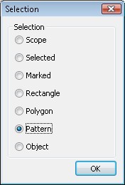
and you can change the plane order based on the object types. Only the object types of the selection will be shown and using the Forward and Backward selections the object groups will be moved keeping the original object plane sequence.
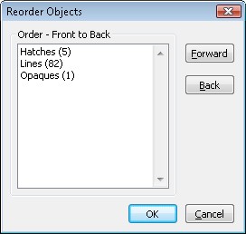
3D Rendering
Whilst not the subject of this FAQ it is worth understanding that only 2D wireframe uses planes. In all other rendering modes it is the spacial position of objects which effect the display.
Applies to
Caddie 14 and later
Question
I have been sent a drawing that was created in another CAD system and all the patterns have been converted into blocks. I would like to remove the block information but retain the pattern information. However when I explode the blocks the objects are not in patterns. How can I explode them and keep thep logically together as patterns?
Answer
If you only want to explode a selection of blocks, first restrict the scope by selecting the required blocks. The way this is done will depend on the drawing. For instance you may be able to restrict the scope by layer, colour etc,. by using the QUICK SELECT option on the context menu. From Caddie 16 the context menu also has the LAYERING & DISPLAY options that may make this easier.
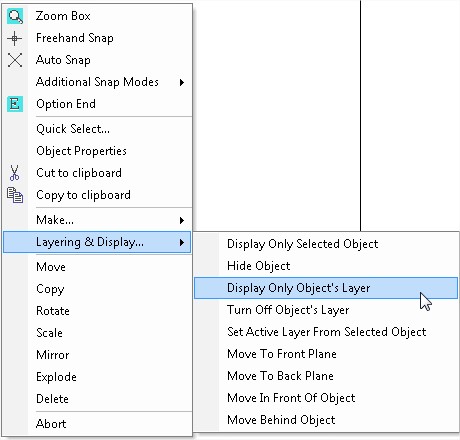
If it is the whole drawing then selection is not an issue.
The next step is to explode the blocks.
To do this go to the EDIT commands and choose Global Explode
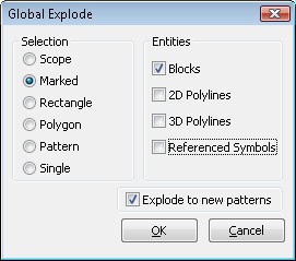
Choose your selection, entities (in this case blocks) and tick the "Explode to new patterns" tickbox.
Caddie will explode all the top level blocks in the selection. If there are nested blocks you may need to do this more than once.
Further Information
Even though the block references have been exploded, the block information is still in the drawing (in the block table). Unless you require these block again it is worth removing them, to keep the drawing size down. To remove the blocks go to
'MENU | FILE | DRAWING UTILITIES | PACK DRAWING'
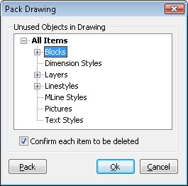
If there are unused blocks in the drawing, 'Blocks' will have a '+' sign next to it. Click on the '+' and either select all of the blocks or the individual ones. You can use the control key to select. Once selected, click PACK.. After packing the blocks, nested blocks may be revealed, so you may need to run the process again.
Applies To
Caddie 16 and above
Question
I have a dimension where the text would be better at 90 degrees to the arrow line. How do I do this?
Answer
This can be done, but only on dimension text that is horizontally aligned.
If need be go to the DimSet dialogue, go to the text tab. Select Text Alignment = HORIZONTAL.
Close the dialogue by selecting the OK.
Draw the dimension(s) as normal, or edit an existing one (DimEdt).
Select the dimension you want to change and go to object properties. Look for the field 'HorText Align' and change the angle to 90 degrees (or any other angle). This will affect all the selected dimensions.
NOTE
This is an override and it will not affect future dimensions, even after a GETDIM therefore a DimEdit doesn't have any effect. Also note that if global styles are used, a change in the dimension text angle will only affect the selected dimensions and not any other dimensions using the same style.
Applies to:
Caddie 12 or later
Question:
I was creating a tool bar using the customise option (right click a top tool bar), and deleted, rather than copied a menu option How can I get it back?
Answer:
Save any drawings and close Caddie and open Caddie. Do this once more and you should see the missing menu.
Alternatively go to 'MENU | SETTINGS | SCREEN LAYOUTS | RECALL SCREEN LAYOUT' and select the required layout. The "Original" layout is the one created when caddie was installed. If the Settings menu is missing, you will need to use the first suggestion.
Applies To
Caddie 16 and above
Question
I would like to save a copy of the drawing that I am currently working on as a copy with maybe a different name or with a different path. When I do a 'FILE | SAVE AS', with a new name or / and a new path, the current drawing name or path changes. This means that a subsequent save will save the drawing with the incorrect information. How do I keep the current name and make a copy somewhere else?
Answer
For Caddie 16 there is a new command, which is 'FILE | SAVE OTHER | SAVE COPY'. Using this command a copy of the current drawing is saved with what ever name or / and folder you want, but the current drawing name and / or folder is preserved. Therefore a subsequent 'SAVE' will use the original file name and path.
Applies to
- Caddie 16
Question
How can you change the format of text within a paragraph of text?
Answer
The DWG format allows MTEXT, the text type mostly used in Caddie, to contain overriding formatting codes. These formatting codes are included with the text and allow enhancements of the characters or words.
If you want to enhance text in a text block (MTEXT) you can edit the text and the require part of the text block can be enclosed with {} and include control codes. So you may want to change some text in a sentence to be have over scores, a different font or a different size etc. The codes used for MTEXT formatting are shown below.
|
Codes for formatting |
||
|
Text Format Code |
Effect |
Entering the following ……. |
|
\Hvalue; |
Changes to the text height specified in drawing units |
{\H2x;This is a test text Current Height x 2} |
|
Result : |
||
|
\Hvaluex; |
Changes the text height to a multiple of the current text height |
{\H250;This is a test text Height 250} |
|
Result : |
||
|
\Tvalue; |
Adjusts the space between characters, from .75 to 4 times |
{\T1.5;This is a test text Character Spacing x 1.5} |
|
Result : |
||
|
\Qangle; |
Changes obliquing angle |
{\Q15;This is a test text Oblique Angle of 15°} {\Q-15;This is a test text Oblique Angle of 15°} |
|
Result : |
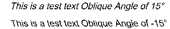 |
|
|
\Wvalue; |
Changes width factor to produce wide text |
{\W0.8;This is a test text Width Factor set to 0.8} |
|
Result : |
 |
|
|
\Cvalue; |
Changes text specified colour |
{\C5;This is a test text Pen 5} |
|
Result : |
||
|
\0 (on) |
Overline ON / OFF |
{\OThis is a test text with Over Line} |
|
Result : |
||
|
\S |
Super Script |
This is a test text with {\H0.5x{\SSuper scipted^ ;}} Text
|
|
Result : |
||
| \L...\l | Underline | This is a test of \LUnderlined\l text |
|
Result : |
This is a test of Underlined text | |
Braces can also be nested to create complex changes.
This example describes how the text in the following illustration was created.

{{\W1.5;The {\H2x;Quick}} {\C14;{\H2x;Brown {\Q20;Fox} }}{\C5;{\T2;Jumped }}Over the {\H75;Lazy} Dogs Back 1234567890}
Restrictions
- This type of text modifications, whislt giving great effect, can slow down the process of entering textural highlights.
- There is now obvious way to see what text has had format codes add without editing the text.
- Editing text format will be limited to one block of text at a time.
- Any preset used within the MTEXT will override any standard settings such as font, size, pen etc.
- Currently there are no format codes for Bold or Italic. If you want a whole block of MTEXT to have Bold or Italic format, right click the font in the Text Set dialogue and select the require format.text
Adding Formats Using the Caddie Text Editor
By using the text editor in Caddie, text can have most of the basic formats added by simply selecting the text and clicking the required format (pen, bold, italic, size etc.). See the help in Caddie "Enter text via Editor" for further information.
APPLIES TO
Caddie 20 onwards
QUESTION
How can I enable through-viewport editing?
ANSWER
To enable through-viewport editing, go to Configure -> Environment Settings. Expand the Viewports option and double click the 'No'. You can then change it to Yes in the combo box. Click OK to save the settings. Through-viewport editing will now be enabled. Double click inside a viewport to edit the modelspace objects.
APPLIES TO
Caddie 20 onwards
QUESTION
How do I stop a spreadsheet that has been inserted into a drawing from updating when the spreadsheet is updated externally?
ANSWER
If you have inserted a 'linked' OLE object into your drawing and you update the object it came from, the version in the drawing will be updated. To prevent this, you must 'break' the link. To do this, select the object then right click and from the CSM choose 'Edit OLE links'. Choose the correct link from the dialogue and click 'break link'
Note that this action cannot be reversed. If you want to re-link an OLE object erase it from the drawing and re-insert it.
OTHER FAQ's
None.
A common question is why with objects selected can't the properties be changed. There are a number of answer to this and it can depend on the type of object that is selected.
Here are a couple of examples.
If a block reference is selected, the objects being displayed are part of the block information and not the selected Block Reference. References have their own properties and it is these that you change with Object Properties.
There are some cases where changing the properties of the Block reference can change the way the contents are displayed. This will only happen if the block objects have there assignments set to one or more of: Pens 'By Block', Linestyles 'By Block' and Pen Thickness 'By Block'. In these cases the contents will be displayed with what ever the Block Refence current properties are.
If the objects being displayed are directly assigned, rather than 'By Block' the block needs to be edited. Note however that all Block references displaying this Block will also be updated. If this is not desirable then either copy and edit the block or if you don't require a block, 'Explode' the reference and then change the properties.
Another reason the selected objects can not be edited is they may be on a locked layer. Go the 'CADDIE | SCOPE | LAYER SET' and check the layer has the 'E' in 'VSE' available. If not select the layer and choose the 'E' flag at the bottom of the dialogue. As a note more that one layer can be changed at a time. Use the standard Windows 'Control' or 'Shift' selection method.
In earlier versions of Caddie Option End on the context sensitive menu could be used to unselect objects.
The selection is vastly more flexible in Caddie 16, with the ability to select by polygon, rectangle, crossing, outside polygon, outside rectangle, etc etc.
Some of these functions require an Option End (similar to mark), therefore Option End cannot unselect objects in Caddie 16.
The context sensitive menu now has an abort option (which has the same functionality as the escape key on the keyboard). Use this function to terminate commands rather than Option End.
Opening a Caddie drawing into other CAD programmes causes multiple objects to be selected when selecting a single object.
Background
In caddie we use a function called Patterns. This is function logically associates all the objects in the Pattern by assigning a unique name all the Patterns objects share. The objects in a pattern can be manipulated (copied, moved, rotated and have their properties changed etc.) either individually, or by using a Pattern command, all at the same time (like a group) without physically locking them together as Blocks would do. This functions is also used by other DWG based drawing systems but the function can have different names, typically “Groups”.
What happens with Patterns (Groups) when opening a DWG drawings in another programme
When opening a Caddie generate drawing in other programs the functionality of Patterns remains the same as it does in Caddie. However the default way in which these are handled in these other programs can be different. For instance some other programmes default to selecting all the objects in a group (pattern) when a single object is selected. To the untrained eye this gives the appearance that the objects are block when in fact they are not.
How to Change the way Patterns (groups) are handled in other DWG programmes
To change the way these groups (Patterns) are treated you may need to check with your software user guide to find what the control is to change the “Select All” function.
As an example you may find that you can toggle group selection on and off by using a keyboard shortcut such as CTRL+H or SHIFT+CTRL+A. Some systems also have settings in the options dialogue for selection. Look for something like “Selection of Object Grouping” or “ Object Grouping”. Also look in your products user guide for the System variable such as “PICKSTYLE”.
Searching the internet using your favourite search engine for “Object grouping DWG” or “DWG PICKSTYLE” will also turn up a number of useful tutorials and help pages.
How To Have a Single Click Selection of Patterns (Groups)
You might be interested to know that the single click selection is an option in Caddie. To set this up go to 'MENU | SETTINGS | MOUSE'. Selectio the 'PATTERN SELECTION' option from the left Single Click drop down.
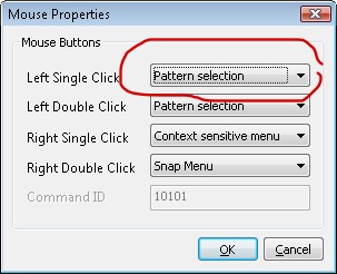
How do you change the views of the Drawing?
When working on a 2D drawing you probably only want to view the drawing by looking down on it. When working with a 3D model you will often require to look at it from different angles.
To change the view to TOP view you can use the TOP command in the 3D application under 3D VIEW (see below)
.
As TOP is the command used the most and usually required when drawing in 2D this command can also be found on the top menu bar:
'MENU | VIEW | TOP'
A tip here is to create a keyboard shortcut of 'T'
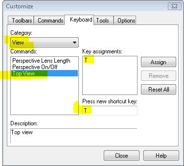
While here we will look at the other 3D View commands related to viewing
The first set are the pre-set positions.
These are TOP, BOTTOM, FRONT, BACK, LEFT and RIGHT.
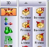
For intermediate control we need to use that other view commands.
The first set of commands are the ROTATE commands.
You can rotate either LEFT or RIGHT.
Each Click is approximately 5 degrees

As this is a little time consuming, you can use the mouse by holding down the CENTRE button (the wheel) and the keyboard SHIFT at the same time and moving the mouse up or down the screen..
The next set of 3D View commands is ORBIT.

You can Orbit UP, DOWN. LEFT & RIGHT.
Again as this is a little time consuming, you can use the mouse by holding down the LEFT button and the keyboard SHIFT at the same time and moving the mouse around the screen.
Another tip well worth knowing is the Zoom. Most people know about using the wheel on the mouse to zoom. When working on a 3D model and in particular when perspective is turned on, the wheel is maybe too course. An alternative is to hold down the CONTROL key on the keyboard and the LEFT BUTTON on the mouse together and move the mouse up and down.
And finally PANNING can be achieved in much the same way, only instead of using the CONTROL key use the ALT key.
This applies to Vector linestyles (those that do not start with a 'P' in the name). There are a number of possible reasons for this.
- In order to speed up the redrawing of the screen, Vector lines will only be displayed with the line style when the zoom level is sufficient to show the style. A 'REGEN' will probably need to be executed before the line styles show. The converse is true when zooming out. Vector lines will show dashed untill a 'REGEN' is executed.
- The more common reason for vector lines showing as continuous lines is the render mode selected. On the bottom status bar the rendering mode can be changed. Only 2D wire frame (depicted as a rectangle icon) will show vector lines correctly.
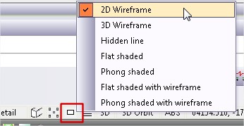
Note:
- The render mode chosen also effects solid fill hatches and opaques With a 3D render mode chosen only lines for the edges of the hatch or opaque will show.
Opaques will only mask the objects behind them if the display mode is set to 2D Wireframe. This is controlled by the icon at the bottom of the screen. Click the icon to change the setting.
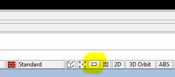
Objects on planes above the Opaque (typically drawn after it) will not be masked, unless you change the display order to move the Opaque plane above the objects (or move the objects plane below the Opaque). You can change the display order using tools in the 'Edit' Menu
You may be running Caddie in Professional, Budget or Educational mode, but Caddie won't allow you to save drawings,
If you get the message that the file is read only and it is i.e. opened somewhere else or from a read only drive, such as a CD, you should be able to save it to a different drive or folder. or with a different name or at least to the desktop or root of you local machines drive if it was opened from a writeable drive.
If you can save it locally but you can't save to a network drive, this indicates a network problem.
You can't save any drawings that have been opened from a CD (or read only device) back to the same or another read only device.
If you try to save a drawing and it says it is read only even if you do a Save As with a new name, it is likely that the issue is not the drawing or the folder but a privileges issue.
A classic scenario is to log on as a guest. Guests, by the nature of what they are, do not have any privileges what so ever, and you will always get the massage when trying to save. Caddie isn't even allowed to do a Backup. A test for this is to try and do a forced backup (FILE | SAVEOTHER | BACKUP NOW).
Using the TAB key, Ctrl key and ‘1’ key to modifying the way Caddie commands work
The TAB key and other modifiers are used in many places within the Caddie environment. The function of these keys is dependent on the command you are using currently.
TAB
Draw Lines
Holding the TAB key whilst drawing lines using Draw or Auto locks the angle to increments set in the ‘MENU | SETTINGS |DRAG SETTINGS’ dialogue.
Lines | Rectangle
If the TAB key is held down when selecting ‘CADDIE | DRAW | RECTANGLE’ a modifier is applied to toggle the rectangle to be drawn the alternate option of either a single Polyline or four Lines, dependent upon the current default setting. Note the setting to determine which option is default is contained within the Registry settings.
Construction lines
When drawing construction through two points (CADDDIE | CONLINES | PNTS-2) the second point is locked to the drag angle.
If drawing a "X" , "Y" or a "Z" construction lines you can specify the end point of the first line, which is then used by all the subsequent ones.
If drawing a line at an angle (CADDIE | CONLINES | PNT-ANG) the construction line starts at the indicated point and is drawn at the specified angle.
Dragging
Any form of dragging will lock to the drag angle as set in ‘MENU | SETTINGS |DRAG SETTINGS’ .
Text | Enter
You can specify in the text set parameters dialogue if you want to be asked for the paragraph width when entering text using the text editor. Whatever you have set here will be negated if the TAB key is held down when entering the text editor (CADDIE | TEXT ENTEDTR).
Patterns | Initialise
If the TAB key is held when Initialising a pattern USING the keyboard ‘i’ or ‘selecting the initialise command (CADDIE | PATTERNS | INTIAL) a dialogue box will be displayed and the name of the pattern can be specified.
Scope | Layer Display
If the TAB key is held down when selecting Layer Display (CADDIE | SCOPE | LAYDISP) the scope will be set to the layer of the next object that you select.
Scope | Patterns (Selecting Multiple)
Using the TAB key when selecting patterns for SCOPE (CADDIE | SCOPE | PATTERN’ allows more than one pattern to be selected for SCOPE. After selecting the Pattern command from the SCOPE menu you will be prompted to Pick patterns to place in scope’. To select multiple patterns, depress the TAB key during the selection process then release prior to selecting the final pattern required. Selecting the same pattern twice will de-select it form the list. Alternatively, to finish your selection and draw the selected patterns to the Scope, press ENTER.
Hatch Origin
You can customise the position the a hatch origin by using the combination of TAB and using ‘CADDIE | HATCH | AUTO’. The default position of the hatch origin is 0,0,0 (the bottom left corner of the model space grey rectangle, or a sheets bottom left corner). If the TAB key is pressed at the same time as clicking the ‘CADDIE | HATCH | AUTO’, you will select the hatch method (inside, endpoints or closed object) then place the hatch in the require way, and then the islands followed by an option end. The next prompt you will get will ask where you want the hatch origin. This is on a one off basis. Selecting the space bar which starts the last command does not show the origin select prompt. You have to press the TAB key and click ‘CADDIE | HATCH | AUTO’ to do that.
Rectangle by 3 Point
By depressing the TAB key at the time of selecting Rectangle by 3 Points (CADDIE | DRAW | REC3PT), you can predefine an enclosing area for the rectangle, additionally, specifying the units for this area, which may be different from the Drawing Units. Perfect for preparing scheme drawings where outlines of room or buildings are required, meeting specific area criteria.
Control (Ctrl)
Context Menu | Move and Copy
When moving and copying objects using the Context menu, and additional Dynamic Rotate function is added to the end of the command by depressing the Ctrl key at the time of selecting the tool. Useful for moving / copying objects and then aligning these to boundaries, for instance.
Number ‘1’ key
Nearest Object Selection Override
You may force Caddie to adopt Rectangle Select rather than Nearest Object Select by depressing the number ‘1’ key prior to commencing your selection. Extremely useful if your drawing contains many objects in close proximity to the area you want to select, or the point at which you wish to start your selection rectangle includes a hatch object.
This is applicable from Caddie 10 onwards
When the drawing was saved previously, either in another CAD package or in Caddie, it is likely that the drawing was packed. This means that all unused items were removed from the drawing. You just need to bring it into the drawing again.
To do this, follow these steps:
Click on “Settings”-> “Drawing Elements”-> “Import Line Styles”
From this list you can click on the either select the desired line style to import, or click on the “Select all” button, and make sure all the line styles are selected, and then press “Ok”.
All the linestyles selected should be in the list now.
See images for reference.
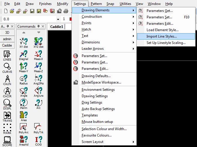
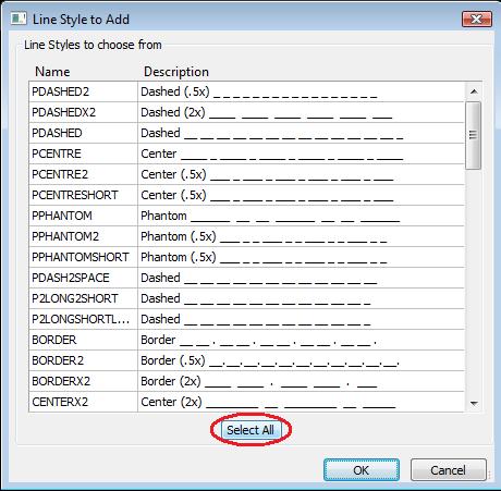
The Scope Toolbar is often underused or is just not understood.
If you are not familiar where this toolbar is, you should find it some where in your screen layout. Find the bar the looks like this:
![]()
This bar maybe docked or (as shown) floating. If you don’t see it check you have it turned on (a tick next to the name) from
’MENU | VIEW | SCOPE’).
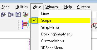
Once you have identified it you will notice there are 9 icons – one for each of the finishes. Hovering over each icon will tell you what they are.
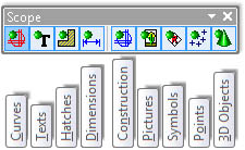
So if you need to temporarily hide all lines, arc, circles and polylines etc. select the first icon. When selected you will notice the DOT changes to RED.
If we select it again the DOT goes GREEN and all the lines are showing and active.
So to apply this to hatch, we select the Hatch icon and its dot changes to RED.
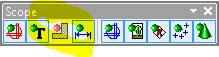
Any hatch in the drawing is now hidden from the scope, in other words, hatch is non-active. This means that anything done to the drawing, such as selection and move, doesn’t affect the hatch.
Therefore after a move, turning the Hatch (Scope Bar) ON (Green Dot) the hatch hasn't been affected by the move
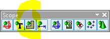
It is also useful to be able to turn off certain finishes when drawing, such as hiding 3D objects, Pictures (includes Opaques), Symbols (Blocks and Reference Symbols) etc. to make selection or modifications easier – “seeing the wood for the trees”.
Also vast amounts of hatch can slow down moving around a drawing, so hiding it temporally can speed up drawings.
NOTE: If any of the scopes are turned off in the model then sheet viewports will not be able to see the hidden objects. So when working on the sheet turn on the Scopes in the model space first.
Setting these scopes in a sheet only effects the sheet where they where set – they are not global. The same is true for the Model.
Also note that the SCOPEALL command or indeed any of the other SCOPE commands effect the status of this toolbar.
AEC
New and Updated Caddie Multi-Panel Door DWA Style with Integral Cill |
|
Download the Multi-Panel DWA HEREDownload Caddie Evaluation HEREPlease Note that not all Web Browsers support this link, so if you are presented with a page of text and symbols, try an alternative Browser. And please feel free to forward this link to any friends or colleagues who might be interested too. |
Automated AEC Sections with additional 2D auto-place roof tiles |
|
|
|
Please Note that not all Web Browsers support this link, so if you are presented with a page of text and symbols, try an alternative Browser. And please feel free to forward this link to any friends or colleagues who might be interested too. |
Automated AEC Sections with additional 2D auto-place roof tiles |
Caddie auto insert,align and repeat roof tile symbols Download HERE
|
|
|
Please Note that not all Web Browsers support this link, so if you are presented with a page of text and symbols, try an alternative Browser. And please feel free to forward this link to any friends or colleagues who might be interested too. |
Automated Area Scheduling from Polylines |
 |
|
Download Automated Area Schedule Styles HEREDownload User Guide HEREDownload Caddie Evaluation HERE |
|
|
|
Please Note that not all Web Browsers support this link, so if you are presented with a page of text and symbols, try an alternative Browser. Forward these links to any friends or colleagues who might benefit from Caddie Auto-reporting and scheduling.
|

Watch the Tutorial Video nowStep-by-step guide to creating Door Window Assemblies (DWAs) |
|
|
Subject: Create your own DWAs Step-by-step easy to follow guide Why watch: Learn how to create your own Door Window Assemblies to model any combination of Doors and Windows for use as multi-panelled windows, shop fronts and more |
|
|
'WOW! I was amazed by just how easy Caddie 20’s ‘AEC Build’ tools are to use, and genuinely gobsmacked at the results I was able to produce in such a short space of time. In just over 20 minutes I managed to produce a complete model of my building, even including the roof, which I could view in the form of plans, elevations, or full-on 3D model.' Peter Fishenden for Quantus Developments Ltd.
And much more - New features in Caddie 20 Download a FREE Evaluation copy to try on your own projects. |
|
|
Watch the Tutorial Video and |
||||
|
Subject: Step-by-step easy to follow guide Why watch: Learn how to set the door type and configure AEC doors styles to use when drawing floor plans and AEC modelling.
Step-by-step easy to follow guide |
|
|||
|
'WOW! I was amazed by just how easy Caddie 20’s ‘AEC Build’ tools are to use, and genuinely gobsmacked at the results I was able to produce in such a short space of time. In just over 20 minutes I managed to produce a complete model of my building, even including the roof, which I could view in the form of plans, elevations, or full-on 3D model.' Peter Fishenden for Quantus Developments Ltd.
And much more - New features in Caddie 20 Download a FREE Evaluation copy to try on your own projects. |
||||
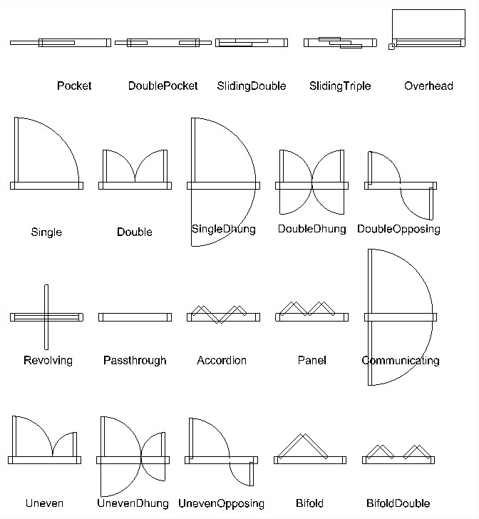
Watch the Tutorial Video and
|
||||
|
Use Your Existing Drawings: Watch the YouTube video See how to create smart schedules and cost estimates from existing plans saving time and reducing errors |
|
|||
Watch the Video and get the DownloadWatch the YouTube video showing how to create the smart schedules from your existing plans, how to update your cost estimates, label the areas you schedule, and keep your plans and schedules in sync to minimise errors. Download the Caddie Magic Schedule Bullet HERE and try it for yourself... Download a FREE Evaluation copy to try on your own projects. |
||||
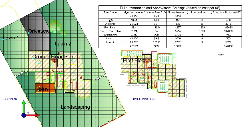
Industrial Unit in ~10 minutesWatch the YouTube video and
|
||||
|
Discover how you can start producing; Plans of your Industrial Unit designs in minutes with short YouTube Video Guide
|
|
|||
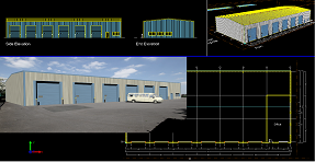
Question:
When a drawing created in Caddie is worked on in some other DWG based systems the linestyle scales of the vector lines sometimes changes with the annotation scale in the modelspace. Can we stop this happening?
Applies To:
Caddie 17 onwards
Answer:
Yes you can. The newer versions of DWG support a system variable called MSLTSCALE. If this is set to False then the linestyles do not scale in the modelspace whereas if you set it to True then they will scale in some software. You can change it in Caddie by going to Utilities -> System -> Set System Variable then following the prompts on the command line, or it can be changed in other fully DWG compatible software by their equivalent tools.
Applies to:
Caddie 17 and later
Question:
I have already drawn a Window using the parameters that I want. Do I have to type in the same parameters again or is there some way of 'getting' those parameters and using them for new windows?
Answer:
In Caddie 17 and beyond, on the bottom right of the Window / Door / DWA dialogues there is a button labelled 'Get Parameters' If you click this button, you can then click on any Window / Door / DWA and Caddie will extract the parameters and populate the dialogue for you, saving you having to type them in.
Alternatively you can select the existing Window / Door / DWA, right click and from the CSM select 'Copy'. Caddie will create an exact copy in the location that you choose.
I have used the AEC tools to create a helical staircase but I can't see how to create a railing that follows the profile of the stairs.
If you select the stair, then right click, and from the context sensitive menu choose AEC -> Railing. To determine different parameters for the railing you can use AEC style manager to edit an existing railing style or create a new one.
Applies to:
Caddie 16 onwards
Applies to:
Caddie 16 and later
Question:
I am drawing a building that requires different walls for each floor. How can I change heights and what are the consequences for other objects such as doors and windows?
Answer:
AEC walls in Caddie are drawn on the current UCS. To draw a wall at a different baseline height, first change the height of the UCS.
To change the height of the UCS go to the 3D tools and select UCS.
At the top of the list there is an OFFSET tool. If you don't know where the current UCS positions is first select the WORLD command. This will put the UCS back to the WCS position.
For the Offset command dialogue change the height to the required value or you could use PICK to select the top of an existing wall.
If you intend to reuse these settings, use the SAVE and RECALL UCS commands at the bottom of the same toolbar.
With the UCS in the new position you can draw walls which will have their base height on the new UCS position.
How does this affect windows and doors etc.
Windows and doors are drawn with the head height referencing the baseline of the wall in which they are to be placed.
So if a window, door or opening is to be inserted in the newly positioned first floor wall, the head height will be, say, 2100mm. If the same window was to be placed in a two floor height wall the head height may be 4500mm.
You can control which part of the wall the door / window etc. is anchored to by selecting it then choosing 'Anchor' from object properties.
Applies To:
Caddie 16 and above
Question:
I am adding an extension to an existing building, but the walls cleanup (merge) with those of the existing building. How can I stop this happening?
Answer:
Walls only clean-up witt other walls in the same Cleanup group. So all that needs to be done is to create a new Cleanup group and assign the NEW walls to that group.
Using AEC Style Manager from the AEC menu go to the section as shown below:
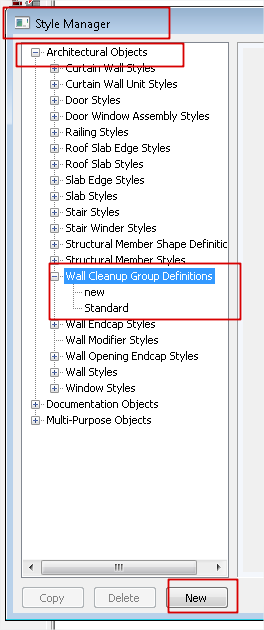
Select the wall Cleanup Group Definitions text and create a New group with whatever name you want.
Once done just reassign the new walls to this group in object properties and the walls will no longer merge.
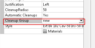
Applies To:
Caddie 16 with Vio
Question
How do I create and change AEC materials used with Vio rendering?
Answer
The best way to render in caddie is to use the, add-on, Vio rendering commands.The description below requires the Vio rendering commands. Assigning renders to standard 3D objects can be done by using the materials tools in the Vio commands. Normally a material would be created and then the material attached to a 3D object by selection, layer, etc. When it comes to AEC objects a different approach has to be taken..
How To Change "db" Materials
All AEC objects are created using styles. If we look at a wall for instance, the wall style may consist of a number of wall components, Brick, Cavity, Insulation, Block and Plaster etc. Each of these components will have been assigned a render when the style was created. To give the user a head start, the standard wall styles already have a render assigned. It is likely that the style will just be a flat colour as a representation, but never the less a quick render could be produced.
All of the currently assigned AEC renders will show in the Materials dialogue once they have been loaded. There are basically two ways these can be loaded.
- The first time the render command is used with AEC object present in the drawing
- Using the Convert Materials Command and selecting DBMaterials from the dropdown
|
Once loaded by either of these methods, the materials dialogue will display the AEC materials as shown. |
|
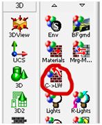
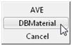
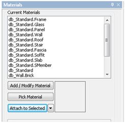
As already mentioned, the normal Pick Material and Attach to Selected buttons are not used with AEC objects. It is the style of the object that assigns the material.
How do we know what materials are used for a particular AEC object.
This can be done by either using the AEC Style manager from the AEC menu or easier is to select the object and from Object Properties select the material option.
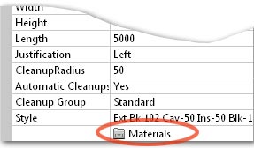
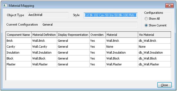
We can’t change the materials here; this dialogue is just used to identify which of the numerous materials is used for a particular component.
Once we know the material we can change it. The easiest material to apply is an image material. This will normally be an .JPG image and can be sourced either from materials supplied with Caddie, your own images or from one of the various internet sites. We will look to change to a pre-defined materials see later in this article.
To change the material for the brick component in the above example, select the db_Wall.brick material from the materials dialogue.
|
|
|
You will notice the current base colour and a reflective colour render for this component has already been pre-set |
|
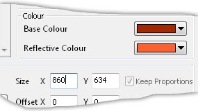
- Tick the Update Texture File tick box
- Browse to the image you want to use
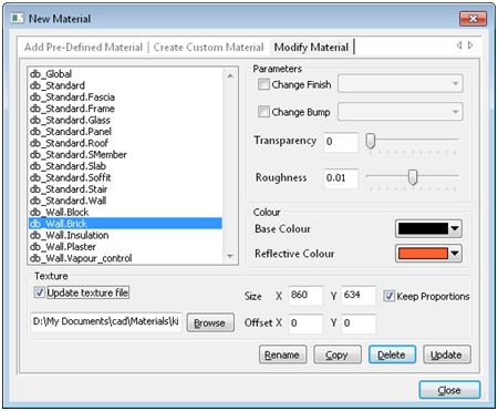
- You will notice the Path and file details have now been entered
- Change the size. By default the size is the actual pixels of the image. However a good rule of thumb is to work out the physical size in millimetres and convert this to pixels. For instance if the image shows 4 bricks wide this would equate to 860mm so enter 860 in the x value. If the Keep Proportions tick box is set, the Y direction will be automatically calibrated
- The Transparency and Roughness can be changed if required
- Select the Update button. The base colour will change, however we are not using it, so it can be ignored
- If you need to, change any other materials by selecting the material and change as above
Now when a render is performed the final rendered image will show the brick in the chosen texture.
Note that all wall styles using this changed “db” material will also be changed. If you require a different texture for some walls, a new style will have to be created and a new material assigned to the component in the AEC Style Manager.
How do I change the material to an internal texture?
Vio has a number of pre-defined materials libraries available. These are accessed from the first tab in the materials dialogue. to modify an existing Pre-Defined material a different method has to be used.
- Select the "Add Pre-Defined Material" tab
- Choose the required material
- Tick the tick box "Change Name"
- Select the " ADD" button
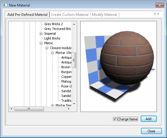
- From the Material name drop down select the name of the material that you want to change
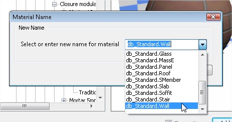
- Select "OK"
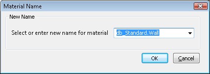
- Say "YES" to the Overwrite Material dialogue
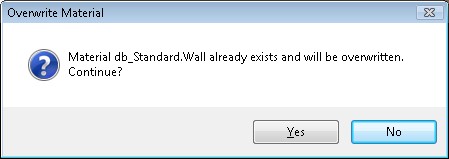
- If you don't need to change any other materials, select "Close" from the initial dialogue.
Basically what you have done is to create a replacement material called db_Standard.Wall
Creating An AEC Material
|
As mentioned AEC objects are defined by their styles. Part of the process in creating a wall is to assign a material to the styles components. With the wall style selected choose the Materials tab. Against each component there is a materials drop down. From this you can select any named material.
|
|
|
If you need to create a new material move down the left menu and expand Multi Purpose Objects and select Material Definitions. Here you will see NEW at the bottom of the list. The name of this material will default to MaterialDefinition_n, where n is an incremental number. The name can be changed by selecting the General tab.
|
|
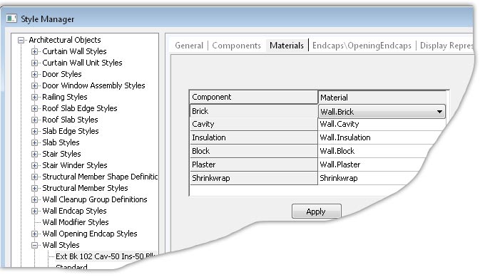
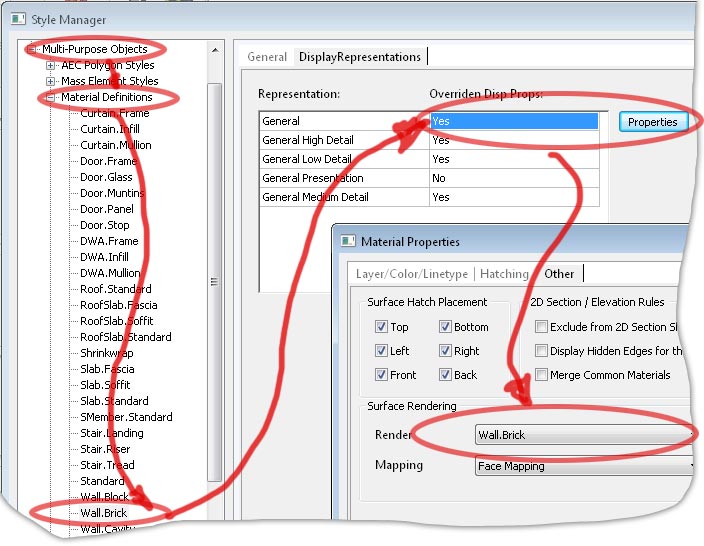
From the Display Reprsentions tab, if there is a NO in the field double click it to change it to YES then, select the Properties button.
In the subsequent dialogue give a name to the material and select the the parameters, such as Diffuse Map (the texture image) or just select an Ambient colour and set any of the other properties. These can of course be change later as has already discussed.
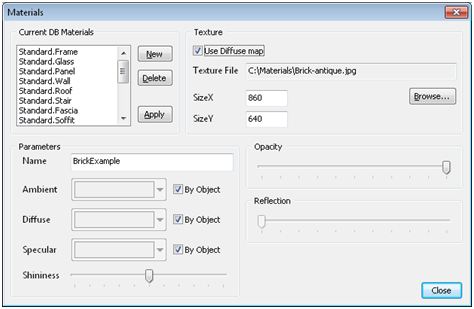
Select Close, Apply in the previous dialogue and close the AEC Style Manager. To see the material in the materials dialogue refresh the list by using the C>LW command as mentioned above.
APPLIES TO
- Caddie 15 onwards
QUESTION
How can I control whether hatch is shown in different wall components in plan?
ANSWER
The hatch will normally be controlled by the material assigned to the component.
Go to AEC -> AEC Style Manager. Select Multi-purpose Objects -> Material Definitions -> Material (where Material is the material definition to change)
Click General then Properties and choose the ‘Layer/Color/Linetype’ tab. Click the ‘Yes (or No) to the right of ‘Plan Hatch’ and at the top of the column choose change the yes to no (or no to yes to switch it on). Click Apply then Close. Finally click Close again to return to the drawing.
Regen the modelspace and the hatch should now be switched off (or on) in that component.
OTHER FAQ's
If you create new AEC objects and want to include them in an existing section or elevation, then you select 'Regen Section'. Select the section to be regenerated and from the dialogue box click the 'Select' button:
select the additional objects with a rectangular selection box then click OK to regenerate the section.
To switch the mitre lines off:
There a two main ways of turning the mitres on or off.
Globally this may be done using the Display Manager. Note this method may also turn other (wanted0 elements on or off.
Open the drawing.
Open the display manager. Select Representations By Object -> 2D Section/Elevation -> General, and set Defining Line to ‘No’.
Regenerate the Sections. See figure below:
The second method uses the properties of the materials to decide if to show the material junction or not.
Using this method you can get Caddie to force the removal of joins to common material. So for instance if two walls use the same material then Caddie will turn off the join.
To access this property, open the AEC Style Manage.
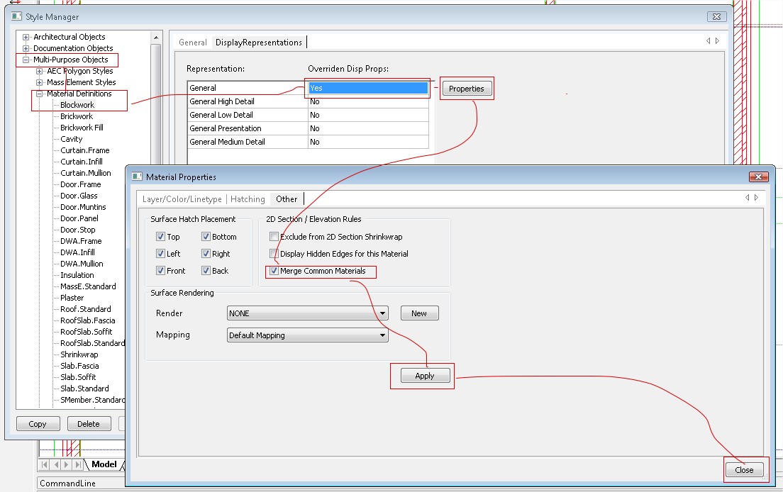
From Material Definitions, find the material that needs changing. Make sure the general section allows overrides by double clicking it. The select "Properties". In the Materials Properties dialogue select the "Other" tab and tick the "Merge Common Materials" tick box. and "Apply". Close the dialogue. Refresh the section and do a Regen. You will find all the materials changed and joining will now have the mitres removed.
Printing
Applies to
Caddie 10 and higher
Question
Where are my plot styles?
Answer
Plot styles in a Caddie DWG (or any Caddie drawing type) are stored as individual files (yourname.ctb) in a plotstyle folder. Also when in the Caddie plotstyle manager (MENU>FILE>CONFIGURE PLOTSYLES) copying, creating or renaning plotstyles will use the desiganated folder.
The actual place where this is will depend the version of your Caddie or your operating system or your choosen location (see below).
Prior to Caddie 16
The default plotstyle folder is in the installed Caddie folder and is called “Ploltstyes”.
From Caddie 16
The folder structure changed and the new position for this folder moved and the location will depend on the operating system.
To make it easy to find the default folders an option was added to the Caddie menu which will take you directly there.
To access this do the following:
MENU>UTILITIES>BROWSE>COMMON APPLICATION DATA FOLDER
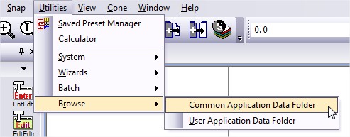
This opens the common folder in a new Windows Explorer window. There you will see the plotstyle folder. Open this folder and drag and drop, paste a copied plotstyle file or note the folder path for the future.
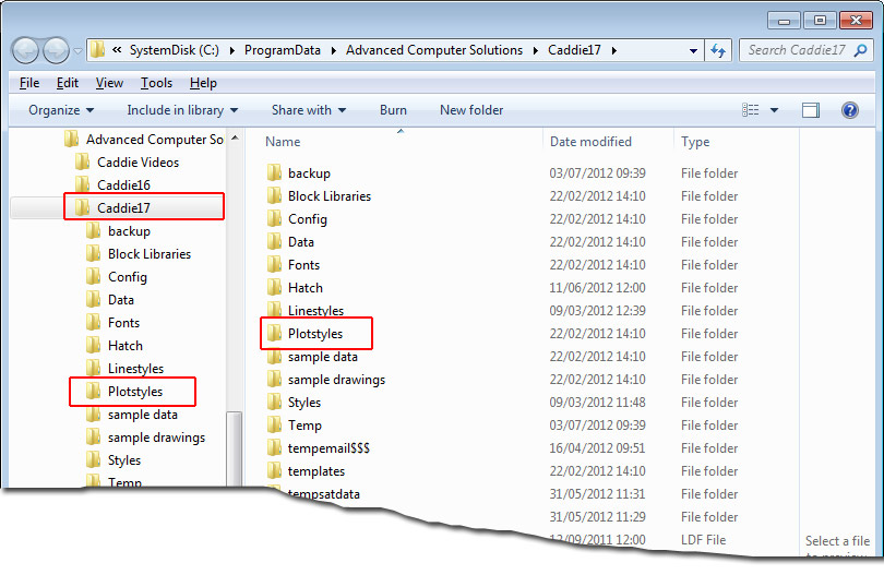
You can also use the Windows search function to search for "plotstyles" or "*.plt" (without quotes) on the C: drive etc. and that will find the correct folder.
Changing the Location of the Plotstyle Folder
If you want to change the folder to a different location, make sure the new location has the required privileges to read and write.
Go to MENU>SETTINGS>ENVIRONMENT SETTINGS>FOLDERS>PLOTSTYLES
Expand the folder and double click the folder path
Select a new path and OK.
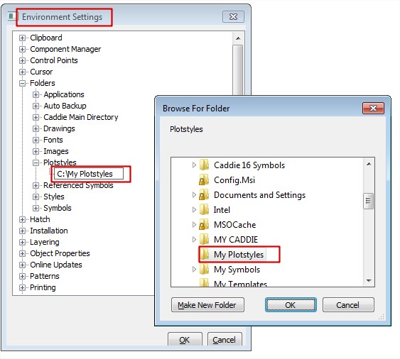
The new path has been selected.
The method mentioned above, used to find the default folder, will still show the Caddie default folder and not your custom folder.
To find where that is at any time, use the same method as when changing the folder. This will show the path which you can then use Windows Explorer to find.,
This method can also be used to find the current location of the plotstyle folder.
How to Specify a Line Plot Width
There are basically two ways to specify a Line width in a DWG drawing (Caddie).
- Defining it in a Plotstyle
- Using the Object Pen Width
Using a Plot Style
The first is to use a plotstyle and to specifically say, that at the time of printing what the thickness of the line should be. The pens used to draw (a line for instance) are chosen from the pen select dropdown (255 available pens plus ‘By Layer’ and ‘By Block’). For more detail on using ‘By Layer’ and ‘By Block’ (see the 'Creating Variable Pen Widths' FAQ for further information). The colour of the pen on the screen is use to represent the pen chosen. At the time of printing (plotting), a plot style file is used to translate the object pens (the screen pens) to a plot thickness and plot colour. These plot styles are saved in the Plotstyle folder.
You can find the current path to this folder by looking at
‘MENU | SETTINGS | ENVIRONMENT SETTINGS | PLOTSTYLES’
The path to your own plotstyle folder can also be set here.
The plotstyle that is used for a particular sheet is set by the sheet setup command (‘CADDIE | SHEETS | SHEET SET’). The plotstyle used by viewports defaults to the same as the sheet, but can be set to a different one by doing an ‘Object Properties’ on the viewport and slecting a different plotstyle.
Editing a Plotsyle
To edit a plotstyle use ‘MENU | FILE | CONFIGURE PLOTSTYLES’. The plotstyle that is set for the current sheet (or model) will be the one shown as loaded. If you require to edit another style select it from the ‘LOAD’ dropdown.
In the illustration below, pen one is directly assigned a custom thickness of 0.13. So regardless of any other settings, the line width will be 0.13mm.
Note: polylines also have a property called ‘constant width’. The default value of constant width is set to ‘0’ and therefore when plotted the line width will be that of the plotstyle. If the constant width is greater than ‘0’ the greater width will be the one plotted.
In theory every pen could have a ‘Custom’ width set in the plotstyle but usually only those required for a pre-set size will be assigned. All others are normally set as ‘Object’ Widths. Object widths are those set directly on the screen. See below and the FAQ
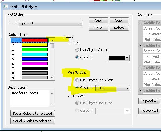
The same dialogue also allows the setting of the colour of the plotted pen.
The choice is
| Object Pen Colour | Set the colour of the Plotted Pen the same as the current screen pen (Object Pen) |
| Custom | Sets the pen from the drop down colour palette |
Again only those required for a pre-set will be set to ‘Custom’ all others are normally set as ‘Object Colour’.
Setting Lines Widths to a Custom Width
The other way set the line widths is to indicate the lines on the screen by using the pen thickness dropdown.
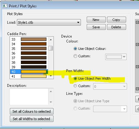
For example, if a line is drawn using Pen 40, intstead of rellying on setting the thickness in the plot style, the thickness can be specified at the time of drawing. In the case 0.35mm is used. Another line could be drawn, also using pen 40, but the width is changed to – say – 2.5mm.
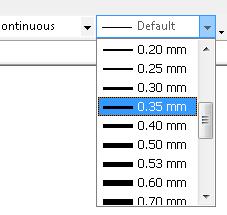
As long as the pen (in this case 40 or 63 hasn’t been pre-set in the plotstyle (it is set as Object Pen Width) you will get a plotted line with a thickness of the object thickness.
If it is required to display these widths on the screen the display widths need to be turned on from the status bar.
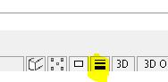 |
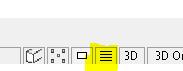 |
| Visibility ON | Visibility OFF |
Use the default object pen width of ‘DEFAULT’ when not specifying the widths on the screen. This may be set directly or ‘BYLAYER’.
By default borders of Opaques show on screen and print. This is a property of the drawing and can be controlled using the following command:
Settings->Drawing Settings->Opaques-> Show boundary->Set to No.
If you are using a template and you set this property to 'No' in the template, then all drawings created based on that template will inherit that setting.
We are always being asked how to create a ‘Boundary’ or ‘Special’ pen.
One way would be to pre-assign a number of pens in the plot style file, specifically for this purpose.
It is quite common to have, say the first 8 or 9 pens, set to progressively thicker lines, with a custom pen colour of, say ‘Black’, There may also be a second set of pen (say 11 to 18) with the units are that same for each thickness as 1-9), but all with a colour of,say, ‘Mid Grey’. These can then be used for any secondary detail such as line hatches, or existing or other building detail.
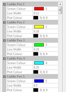
First 5 Pens
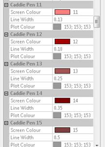
A Set of Grey Pens
If you want sets of extra colours such as red, green an blue, for boundary lines etc., you soon start to eat into the remaining 255 pens. This reduces the number of pens that can be set as ‘Object Colour’, which you may want to use for hatch etc. Not only that, you will have a lot more pen numbers to remember.
A way around this, for these ‘little used pens’, is to have three pens (80, 160 & 240 as an example) set in the plot style. These are set with a custom colour of GREEN, BLUE and RED respectfully and thickness set to ‘OBJECT’
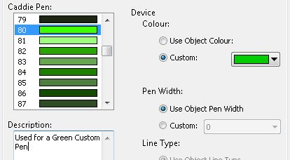
Settings for a Green Custom Pen
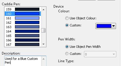
Settings for a BlueCustom Pen
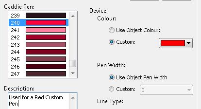
Settings for a Red Custom Pen
As a note, the maximum pen thickness that can be set is 2.11mm. There are a number of solutions to creating thicker lines.
- The first is, simply, to draw parallel lines with an offset of just under the current thickness. This howe ver makes editing any changes more complicated but this can be done with lines, arcs and polylines etc.
- A better solution is to draw with polylines. Polylines can have an additional properties, one of which is ‘Constant Width’. To change this width, select the polyline. Using ‘object properties’ change the width to the required thickness
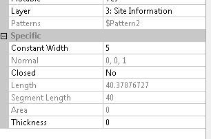 .
.- To change the width of an individual segments, start and end width, use the ‘CADDIE | MODIFY | MODPOL’ command.
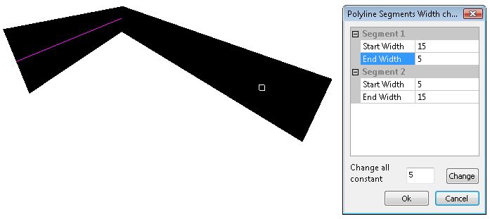
Selecting 'CHANGE' will change all segments to a constant, specified width, which is the same as using object properties.
Another polyline property that can be set in ‘Object Properties’ is ‘Thickness’ and this gives a thickness in the Z axis. This is not, normally, used for 2D drawing.
NOTE: When editing a polyline using the 'CADDIE | MODIFY | POLYLINE' commands, such as 'Insert Node', any existing thickness will revert to '0'
There is a well documented PDF problem that effects many Windows programs with regard to the way PDF’s handle ‘Vertices’. You don’t need to know what the are except the gradient hatches, in Caddie, which are described by the OpenGL commands, can have a lot of vertices.
When creating PDF’s you may need to change the settings in you PDF writers preferences.
To do this open up the preference dialogue by right clicking your printer. All printers have different dialogues including PDF writers. You need to look for an ADVANCED button (as shown in a CUTEPDF preferences dialogue) and you will get a dialogue similar to the one shown below. In the POSTSCRIPT OPTIONS section look for the Postscript Level and change it from 3 to 2. You only need to do this once. Setting it to PS Level 2 shouldn’t effect any other programmes use of this driver, but if it does then temporally set it back to L3.
If Level 2 doesn't work for you try Level 1
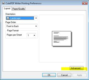
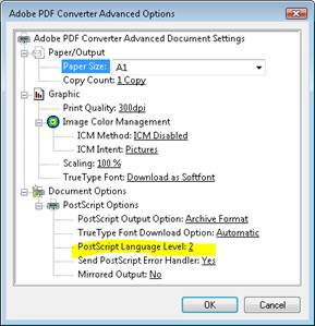
Pre-purchase Help
A Caddie Student licence is a free time limited licence to use Caddie for educational purposes only.
Term of licence
If the licence is assigned to a registered student, the licence is valid for as long as the student is in full-time, or part-time education, however the licence will require re-activating every 12 months.
If the licence is assigned to a company or organisation for use by a registered student (or students), the licence is valid for 12 months.
Restrictions on use
The student licence may only be used for educational purposes. It does not permit the use of Caddie for commercial, professional or for-profit purposes.
Portability
The student licence will be licensed on 1 (one) computer. The licence cannot be transferred without re-activation. The licence is a software licence and will be destroyed if the hard disk of the computer is reformatted. The licence will require re-activating should this occur.
Activation
The student licence requires an internet connection or email facility for activation. If the licence is assigned to a registered student, the licence is valid for as long as the student is in full-time, or part-time education, however the licence will require re-activating every 12 months.
Restrictions on software
A student licence has the functionality of a full Caddie Professional licence including Caddie Vio, photo-realistic rendering. However drawings created in a student licence will always plot with a watermark stating that the drawing is an educational drawing. If any part of an educational drawing (including symbols, blocks, etc.) is imported or merged with a non-educational drawing, that non-educational drawing will immediately become an educational drawing and will plot with an educational border thereafter. A commercial version of Caddie will warn the user, if they attempt to merge any part of an educational drawing into a commercial drawing. If the user ignores the warning and continues to import the educational drawing, then that process is not reversible.
Caddie runs on Windows operating systems. If you want to run Caddie on a Mac you will need to run Windows on the Mac either as a virtual machine of through Bootcamp.
Caddie 19 has been successfully run on an Intel based Mac through VMWare, Parallels and Bootcamp on Windows Vista Windows 7 and Windows 8 / 8.1 (Bootcamp and Parallels).
Please note that our support staff can assist with Caddie issues but are unable to assist with configuring VMWare, Parallels or Bootcamp. We are unable to guarantee the compatibility of Caddie with any Macintosh computer.
Additional information for users running Windows as a virtual machine:
You need to ensure that your Windows virtual machine has access to the USB port so that Caddie can recognise the dongle. If the light on the dongle is not illuminated then either the virtual machine does not have access to the USB port or the Hasp device driver has not been installed correctly on the virtual machine.
Project Tracker
Articles relating to Caddie Project Tracker
Always make a copy of any template before you modify it.
Project Tracker Templates are Excel .xlsx files so can be modified in Excel.
The location of the templates can be found from the System Tab on the Project Tracker Manage page
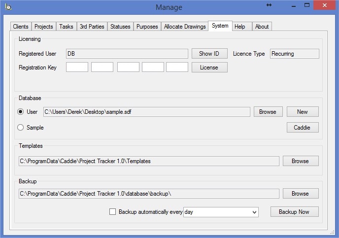
Project Tracker uses Named Ranges to determine where to enter information into the templates. If you delete a Named Range, Project Tracker will not be able to enter the required information and may throw an error.
You can see a list of all the Named Ranges and their locations by going to the 'Name Manager' on the 'Formula' tab of Excel
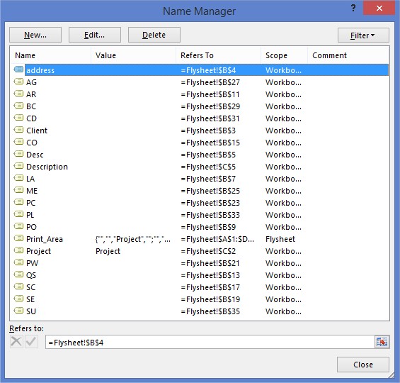
You can make any changes you like to the template as long as you do not erase any of the Named Ranges.