- +27 12 644 0300
- +44 1234 834920
- This email address is being protected from spambots. You need JavaScript enabled to view it.
Articles
How Can Coordinates be Specified on the Command Line?
- Details
- Parent Category: FAQs
- Category: General
- Created on Wednesday, 30 March 2011 18:45
- Hits: 12429
Applies To:
Caddie Version 11 and later
Question:
What are the different ways a co-ordinate can be specified.
Answer:
Understanding the coordinate system in Caddie
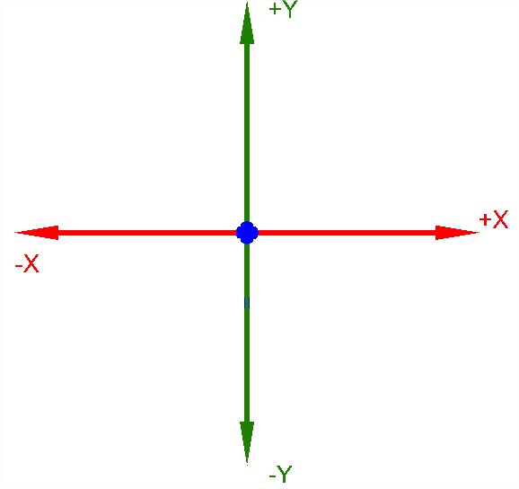
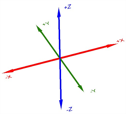
The coordinate system is based on three directions, “X”, “Y” & “Z”. The point the three axis cross is zero and is known as the origin. Assuming a top view, the “X” axis travels horizontally, the “Y” axis vertically and the “Z” axis perpendicular to the screen.


Looking at X in the figure above, the point of intersection is zero, distances to the right are positive and distances to the left are negative.
The position in the drawing where values are calculated from can depend on the setting of the 2D /3D and the mode flag we are using.
2D v 3D
Setting the 2D flag to 2D will override all height information and set the height to zero on the current UCS. Setting to 3D will take in to account any Z height values
Absolute v Relative
If we are using an absolute system (ABS on the status bar) the value will be bases on the current User Coordinate System (USC) origin.
![]()
When REL (relative) is set on the status bar, all coordinate measurements will be calculated from the current origin in the drawing (usually the last position selected).
![]()
Entering coordinate values in Caddie
Specifying Position (UCS)
The principle way is to specify the X, Y & Z values. This is entered in the form of
X,Y,Z
Caddie requires the first two values to be specified (X & Y) and an optional Z value. The Z value can be omitted if the value is zero.
If REL is set the Z value will be ignored and the height set to zero on the current UCS.
Specifying Position (WCS )
If the x,y,z value is prefixed with a hash (#) the values will be measure using the World Coordinate System (WCS) as the reference.
#X,Y,Z
If REL is set the z value will be ignored and the height set to zero on the current UCS.
Specifying a Single value
If a single value is specified followed by a return, the value will only be the distance . The direction will be dependent on the current position of the cursor. If a snap is indicated, this snap point will be used for the end direction.
The 2D / 3D flag will have an effect on the length of the line.
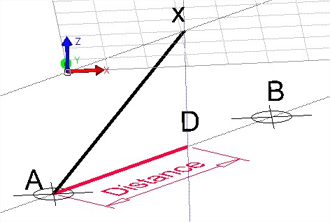
Look at the illustration below. The UCS original position is at the height of the two construction points and the lower construction line. With the 2D / 3D flag set to 3D a line was started at the construction point A. Setting the flag to 2D the second position was specified with only the distance and the snap set to the construction point B. What has happened is the distance has been correctly used (Point D) but the line has been drawn on the offset UCS (x). The vertical (blue) construction line clearly show that the second point is vertically above the specified distance from point A.

Specifying a Distance and Angular Direction (UCS)
To enter a distance and angular direction use the form
distance 3000<-30 will give a value from the current origin of 3000 with an angle of -30 degrees. This is based on the UCS.
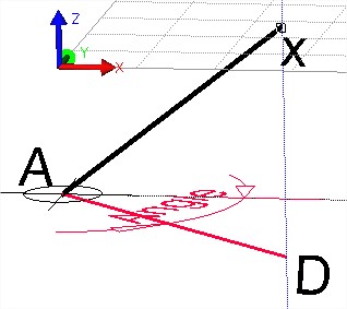
The 2D / 3D flag will have an effect on the length of the line but not on the angle. Look at the illustration below. The UCS original position is at the height of the two construction points. With the 2D / 3D flag set to 3D a line was started at the construction point A. Setting the flag to 2D the second position was specified with only the distance and angle (distance

Specifying Using the Keyboard Arrow keys (UCS)
On the keyboard there are four Arrow keys. Up, Down, Left and Right. Entering a single value followed by one of those four keys, will set the next origin at the distance specified and in the orthogonal direction (UCS) indicated by the key pressed.
The 2D / 3D flag will have an effect on the length of the line. In a similar way to the two illustrations above. A line is started, with the 3D flag set and the first point indicated somewhere other than on the UCS. With the UCS offset and the 2D flag set the point is specified with a value and a cursor key on the keyboard. The line will be attempted to be drawn with the distance and direction stated. However because the UCS has been offset and the 2D flag is set, the end of the line will be on the UCS vertically above the apparent end point.


