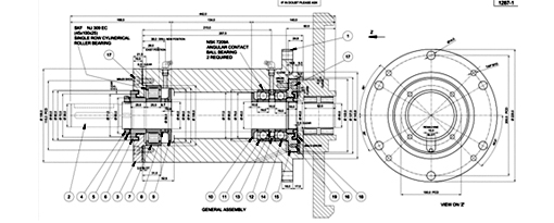
Caddie Mechanical Application

The Mechanical application that is standard in Caddie is a very powerful tool for the designer or draughtsman that needs to prepare documentation and drawings quickly and accurately.
The application has a number of commands in various disciplines of mechanical design that have been developed with industry standards in mind, as well as practical tools to maximize production and speed of design and drafting. Specifications and parametric input gives the user of Caddie mechanical the edge when documentation is being prepared. The process is user friendly and cuts out a lot of manual processes that occur in other software.
Caddie uses the industry standard DWG drawing format, and also supports STL & DXF export, enabling the mechanical application to be used for the preparation of profiles cut by milling machines and wire cutters. The easy profile creation using lines, curves, polylines and splines is well suited for this.
The Caddie Mechanical Application Provides You With:
Intelligent markers and mechanical symbols
Datum marker and machine symbols as well as geometric symbols are used with datum surfaces and roughness indicators. Placement is made easy by simply indicating the surface and then the direction on the correct side.
Tolerances and fits
Automatic tolerance and fit types are provided. No need to look up tables any more, as fit selections are provided on screen. Dimensions are corrected automatically using this feature again saving time.
Balloons and Numbers
Balloon and numbering features are provided. These will auto increment and count automatically, according to settings specified by the operator; thus making notation on documentation easy and consistent.
Pipes and centre lines
Pipe layouts with variable pipe diameters and bend radii can be automatically drawn. Pipes can automatically be created with or without flanges, as required; determined simply by options on a dialogue box. Centre lines are easily inserted into any radial construction.
Bolts, nuts and PCDs
The parametric generation of bolts, nuts, holes, tapped holes and countersunk holes are a huge advantage in the preparation of documents, saving the operator from having to create each nut, bolt and thread manually. PCD options are available on any of the above design entities.
ISO symbols and diagrams
Caddie mechanical allows for isometric symbol placement and electrical diagram generation. Placement, trim and rotation of symbols is automated with little effort by the operator.
Sheet metal and tool paths and welding symbols
Sheet metal development at 1:1 scale is achieved by completing standard templates such as hopper and general square to round development. Tool paths for cutting of profiles, links and sliding link profiles are catered for. Caddie also provides time saving tools for the insertion of all basic butt and groove welding symbols.
The Caddie Mechanical Application is included as standard with Caddie Professional

