• +27 12 644 0300
  • +44 1234 834920
  • This email address is being protected from spambots. You need JavaScript enabled to view it.

When should a licence be moved from one machine to another?

A softlock should be moved from one machine to another when the user wants to use Caddie on a different machine permanently, or prior to a machine having a disk changed, formatted etc., after which it can be moved back if required

The process involves 3 stages:

·        Obtaining the ID file for the destination machine

·        Removing the licence from the source machine

·        Applying the licence to the new machine

Obtaining the ID file for the destination machine

On the destination machine open a browser window and type in the address: http://localhost:1947

The Sentinel ACC (Admin Control Center) should open. If it doesn’t, reload the Caddie Hasp Drivers.
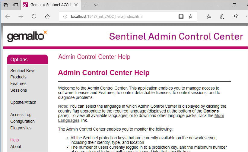
Select Diagnostics from the left menu

Click the Create ID File, as shown above. Save the file. This is the unique ID of the destination machine and is needed in the next stage.


Removing the licence from the source machine

Start the Caddie_Remote_Updater.exe program. On a standard installation it can be found in:

C:\Program Files\Caddie\Caddie xx\Tools\caddieinfo where xx is the version of Caddie

Select the ‘Transfer Licence’ Tab
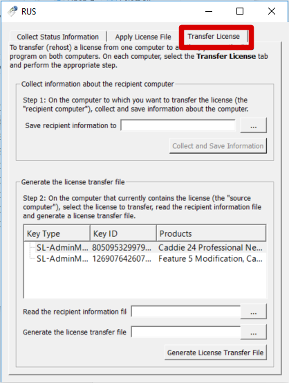


At the bottom of the dialogue there are three options you must complete:
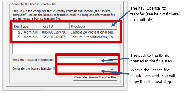

 When you have completed the options, select ‘Generate Licence File’ and a file containing the licence will be created with a suffix of ‘h2h’ (host to host).


Applying the licence to the new machine

Copy the file created above to the destination machine. On the destination machine open a browser window and type in the address: http://localhost:1947. Select the ‘Update/Attach’ option from the left hand menu.
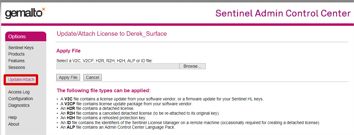
Use the browse button to browse to the h2h file you have just copied, select the file then click the ‘Apply File’ button. Check the text in the middle of the page to ensure the licence has been transferred successfully.

Notes:

1. If there are several licences on the source machine, check to see which licence Caddie is using prior to transferring it. To do this, close all active programs then start Caddie, then in a browser window type in the address: http://localhost:1947. With ‘Sentinel Keys’ selected in the left hand menu, look at the ‘Local’ licences and check which one has active sessions. Note the key ID on that row. This is the Key ID you want to transfer.


2. If you are using any version of Caddie prior to 24, you will also need the matching activation file for your dongle. Having transferred the licence, if Caddie starts in demo mode, from the top menu select Help -> Dongle Info
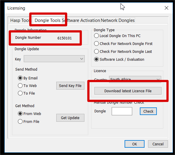
Choose the ‘Dongle Tools’ tab. Check that the dongle number shows correctly, then click the ‘Download latest licence file’ button and follow the prompts. This step is not required from Caddie 24 onwards.


If after creating 3D points from 2D points in the DTM commands the resultant points have a height of "0" we need to look at the text in more detail. 

The text you see on the screen may be the result of some text formatting, and this does not show the added formatting in the text.

For instance the screen text may look like this 184.40 but if the text is edited (CSM>Edit Text) and the "Show format codes" tick box is ticked the you will now see any codes used for the displayed text. It may look like this - {\C256;184.98}. For the details of what the codes mean you can search the help from within Caddie for - Enter text, Text Format or Special Characters.

To remove the format of a single Mtext object, select the text on its own and from the CSM>Text>Remove format Codes.

This is great for a single paragraph of text however we are likely to need to do this for all the height text in the drawing.

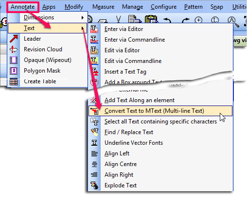
To do this we need to first isolate the Mtext we need to change. This can be done in many ways and will depend on the current drawing. If this drawing has used layers for the Mtext then isolate the text by displaying only the layers. Now select all of the Mtext (if you have isolated the Mtext use Ctrl-A). From the CSM choose explode and exploded the Mtext. The text now is converted to MText. The 2D to 3D points command only works with Mtext, , so this has to be converted back. To do this select the command 


Applies To:

Caddie 16 or later

Question:

I have a very large image I need to insert into a Caddie drawing. What is the best format to do this?

Answer:

When inserting very large images into Caddie the best image formats, are ECW and JPEG2000. 

ECW is the format used for vary large terrain type maps, such as those from satellite images. Normally images of this type will already be in the ECW format. If you wish to convert an existing image to this format, you will need an external converting programme.

The other format is the JPEG2000 (or JP2) format. This is the recommended format for large images such as scans from an existing drawing in high resolution. For instance an A1 drawing scanned at 600dpi.

Modern scanners and output devices may be able to create these images in the JPEG2000 format. However if you are unable to create the JPEG2000 format, or you already have your image in another format, you can use the internal converter in Caddie.

This is accessed from Convert on the Modify Menu.

convert image jpeg20001

  • Select Convert Image to JP2000
  • From the explorer window select the file you wish to convert
  • Select the folder where you want to save the image

A new image in the format of JPEG2000 with the existing name is now saved in the suggested folder.

The existing image is still intact.


Opening a Caddie drawing into other CAD programmes causes multiple objects to be selected when selecting a single object.

Background

In caddie we use a function called Patterns. This is function logically associates all the objects in the Pattern by assigning a unique name all the Patterns objects share. The objects in a pattern can be manipulated (copied, moved, rotated and have their properties changed etc.) either individually, or by using a Pattern command, all at the same time (like a group) without physically locking them together as Blocks would do. This functions is also used by other DWG based drawing systems but the function can have different names, typically “Groups”.

What happens with Patterns (Groups) when opening a DWG drawings in another programme

When opening a Caddie generate drawing in other programs the functionality of Patterns remains the same as it does in Caddie. However the default way in which these are handled in these other programs can be different. For instance some other programmes default to selecting all the objects in a group (pattern) when a single object is selected. To the untrained eye this gives the appearance that the objects are block when in fact they are not.

How to Change the way Patterns (groups) are handled in other DWG programmes

To change the way these groups (Patterns) are treated you may need to check  with your software user guide to find what the control is to change the “Select All” function.

As an example you may find that you can toggle group selection on and off by using a keyboard shortcut such as  CTRL+H or SHIFT+CTRL+A. Some systems also have settings in the options dialogue for selection. Look for something like “Selection of Object Grouping” or “ Object Grouping”. Also look in your products user guide for the System variable such as “PICKSTYLE”.

Searching the internet using your favourite search engine for “Object grouping DWG” or “DWG PICKSTYLE” will also turn up a number of useful tutorials and help pages.

How To Have a Single Click Selection of Patterns (Groups)

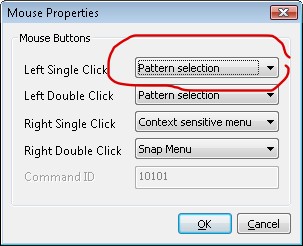
You might be interested to know that the single click selection is an option in Caddie. To set this up go to 'MENU | SETTINGS | MOUSE'. Selectio the 'PATTERN SELECTION' option from the left Single Click drop down.

mouse properties


Applies To:

Caddie 10 and later

Question:

I select some objects and I want to place them at a specific distance and direction relevant to where I pick the object from. I specify it using a X ,Y  & Z co-ordinate but the object ends up in a completely different position. Why is this and how can I stop it happening?

Answer:

There are two ways in Caddie that the measurements are done.

ABSOLUTE (ABS) the default in Caddie

flag absolute

Absolute will always make measurements from the UCS origin by default

So 0,0,0 will be the Zero Origin of the User Co-ordinate System (UCS). The UCS is on the World Co-Ordinate System (WCS) by default.

The UCS can be moved, so therefore the absolute position is also moved.

If when typing in the x,y,z co-ordinate value, it is preceded by a hash (#) - #0,0,0, the absolute measurement is made from the absolute position of the WCS.

RELATIVE (REL)

flag- rel

Relative measurements are always taken from the current origin in the drawing, which is indicated by a small white rectangle.

Conclusion:

The reason your selected objects where moved to a position which you were not expecting was probably due to the fact the ABS flag was set and not the REL flag.


© 2025 Caddie Limited. All Rights Reserved.