As a drawing progresses, you will want to position information on your drawing by referencing that which has been drawn so far. For example, you may wish to use construction entities to set out a section relative to an elevation or a second view relative to the first. To do so you will need to position the construction entities to run precisely through specific points of your first drawing, through end points of lines, through centre points of lines and perhaps through points where two lines cross each other. The latter is known as an intersection of two lines. Caddie provides you with tools to lock onto any type of point. These tools are called snap modes.
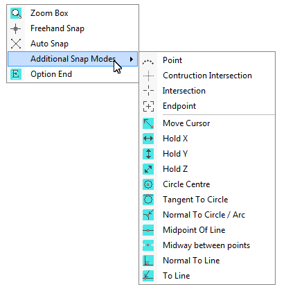
Snap modes are accessed by clicking on the right hand button of the mouse (for a right handed mouse), whilst the pointer is in the drawing area. The context menu will appear. Any snap mode is selected by pointing to the snap mode you want to use and clicking on it's icon with the left hand button of the mouse. When you do so two things will happen. The icon menu will go away and the shape of the pointer will change. Each snap mode uses a differently shaped pointer. By recognising the shape of the pointer you will know which snap mode you are currently using and this will save you going to the icon menu to choose a particular mode if you are already in that mode. The context menu always presents two snap modes (Freehand and Autosnap) the most common snaps will appear in a secondary menu by hovering over "Additional Snaps"
Also See Polar Snap
Move Cursor
If a snap mode is not shown on these two menus then it can be found by going to the SNAP menu and selecting the relevant category. If a more permanent display is required, you can turn on one of the standard snap mode tool bars by turning it on from the VIEW menu. Alternatively you can create your own tool bar - see Configuring & Creating Toolbars
When you select any of the following (grey) snap modes, Caddie will remain in that snap mode until either you select a different mode or you use a Caddie command that changes the snap mode automatically for you. The exception is the grid snap which overrides all other snaps when on.
Selection
|
Screen |
Description |
|
|
Construction Intersection – Search the immediate area around the cursor for the nearest intersection between two construction entities |
|
|
Intersection - Search the immediate area around the cursor for the nearest intersection between two construction and/or drawing entities |
|
|
End point - Search the immediate area around the cursor for the nearest end point of an entity. |
|
|
Freehand - Freehand snap mode has no snap condition and allows you to indicate any point on the screen.
|
|
|
Point entity - Search the immediate area around the cursor for the closest point entity |
|
|
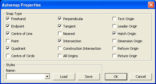
Auto - Search the immediate area around the cursor for the closest intersection of any entities, or an end point and snap to that intersection or point. If no point matching these conditions is found snap to a freehand position. You can also set up the auto snap to the new Auto-snap type by right clicking on the auto-snap tool in the right click tool box. With the new auto-snap an indication of the snap point and the element associated with it are high- lighted. By going into the properties dialogue box you can choose what will be snapped and the way the indicated snap is displayed. (see below) |
|
||
|
|
Grid Snap. This snap is a toggle snap. That is you the state is changed by selecting it. It is on when green and off when grey. When on (GREEN), the over ridding snap will be the nearest grid point. Any other snap currently set will only be used if a grid point is not found in the local proximity. The grid size is set up from |
The dialogue shown above is where the Auto Snap preferences are set. This can be found by selecting Snap and AutoSnap Settings from the Menu bar
Intermediate snap modes are selected in a manner similar to the snap modes above. The difference between them is that intermediate snap modes are only active for a single entry.
The available intermediate snap modes are
|
|
Move Cursor - Move the cursor to a position in the drawing area before entering the next point. |
|
|
Tangent to a circle or arc - Search the immediate area around the cursor for the nearest circle or arc and snap from the last entry point to the nearest tangent point on that entity. |
|
|
Circle or arc centre point - Search the immediate area around the cursor for the nearest circle or arc and snap to its centre point. |
|
|
Normal to Circle or Arc Search the immediate area around the cursor for the nearest arc or circle and snap perpendicular to it from the last entered point. |
|
* |
Hold Horizontal - Keep the vertical coordinate constant from the last entry point. |
|
* |
Hold vertical - Keep the horizontal coordinate constant from the last entry point. |
|
|
Midpoint of a line - Search the immediate area around the cursor for the nearest drawing entity and snap to the midpoint of that entity. |
|
|
Spline Intersection - Snap to the intersection of a spline and a line, arc or circle. NOT IMPLEMENTED |
|
|
Line end snap - Search the immediate area around the cursor for a line and snap to the nearest end of it - the end maybe outside the visible area. |
|
* |
Midpoint of two points - Snap to the mid point between two indicated points. |
|
|
Line snap - Search the immediate area around the cursor for the nearest line and snap to the nearest position along the line |
|
|
Normal to a line - Search the immediate area around the cursor for the nearest line and snap perpendicular to the line from the last entered point. |
|
|
Two Line Projection - Finds the truncated or projected intersection of two lines |
|
|
Text - Snap to the origin of text |
|
|
Dimension - Snaps to the origin of dimensions |
|
|
Hatch - Snaps to the origin or nodal point of hatch |
|
|
Leader - Snaps to any leader nodal point |
|
* |
|
|
* |
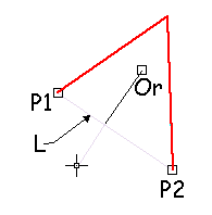
Using this snap mode an imaginary line is draw between two points as the line of snap. In this case a line (Or) is draw until it meets the defined snap line (L) which the end points are defined as being P1 & P2. |
|
* |
Select the line which will be used for the Snap Drag. The place on the line that is the snap point is the point at which an imaginary line (L) drawn from the cursor meets the line at right angles. So in this case a line drawn from the start point (Or) will snap at the right angle point to the cursor where it meets the red line. This is also useful to be able to extend lines and keeping the same axis as the original line. This command only works with lines. To extend lines, arcs, and polyline line and arc segments, there is an additional option on the CSM snap modes called Extension. see Polar Snap for more details. |
There are three commands on the icon menu that do not fall into the category of snap modes. They will be described here for the sake of clarity. |
||
|
|
Option end - The option end command is used to terminate commands, or in commands, which require an indeterminate number of entry points that must be entered before the command, can be processed. |
|
|
Zoom box - The zoom box command is used to zoom in to part of your drawing i.e. magnify a portion, to aid drawing. Two diagonal corners are specified to select the area into which to zoom. Right clicking this tool expands the selection. |
|
|
Properties - After this has been selected the object type will be displayed on the screen as the cursor is passed over the object. Left clicking the input device will open the relevant property dialogue box. Certain sections with in this box allow modifying attribute to the object. For instance the layer can be changed for most objects. See Also Interrogating and Setting Object Properties |
In addition to the above snap modes there are a number of 3D snap modes
|
PrH>Pl |
Project a
point onto a plane parallel to the UCS |

|
PrP2P |
Project a point onto an imaginary line
between two points |
|
PrLiPl |
Project
a line (or construction line) onto a plane |
|
Pr2PPl |
Project
two points onto a plane |
|
Pr2PUCS |
Project
two points onto the UCS |
|
PrLUCS |
Project
a line (or construction line) onto the UCS |
|
Pr>Pl |
Project
a point normally onto a plane |
|
PrPlUCS
|
Project a point onto a plane parallel
to the UCS |
Also See


.png)


.png)


