COMMAND: Set dimension parameters
AIM:
Select the different dimension parameters from a dialogue box.
EXECUTION:
This dialogue can be displayed in a number of ways.
![]() Use the Dimension Parameter Setting tool found on the Dimensions tool bars.
Use the Dimension Parameter Setting tool found on the Dimensions tool bars.
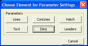
![]() Use the Settings Menu and select the option for parameter set which displays the following dialogue,
Use the Settings Menu and select the option for parameter set which displays the following dialogue,
where you can select Dims
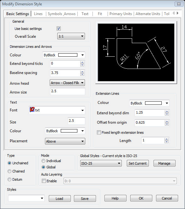
Either way will invoke the settings dialogue box shown below.
Before we talk about the settings available for dimensions, we need to understand how we set the parameters of a particular dimension.
You can either set an individual dimension's parameters directly, known as "Individual Mode", or you can assign a dimension to use a preset style, known as a "Global Mode".
If a dimension is set to a global mode, its parameters will be the same as any other dimension that uses the same global mode style. If the global mode style is edited, all the dimensions using that global style will also reflect the changes.
You may only want to change the parameters of an individual dimension without effecting any other dimensions. To do this you can either:
Edit the parameters by telling Caddie this will now be an individual dimension and all the parameters will be set explicitly for that dimension.
Or
Create a new style with the required parameters and assign that style to only the required dimension.
Getting the parameters from a particular measurement using the Get dimension parameters command will get that dimensions mode. So if the selected dimension was set to use global mode then once the Get command was executed all following dimension commands will use the selected global mode. Similarly if the dimension that we were getting the parameters from was set to individual mode all further dimensions would be set to individual.
The dialogue box is divided into a number of TABS and a common bottom section.
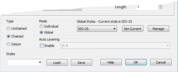
At the bottom of the dimension parameter set dialogue box is a section which is not only common to all the tabs but also sets the way in which the dimension will be drawn.
This set how the way the dimension is drawn.
When selected all dimensions placed will require a starting point and an end point.
When set, the first dimension (A) placed will require a starting point, an end point (B) and a text position (C). All subsequent dimensions (D & E etc.) will only require an endpoint. The following dimensions start point is automatically the end of the previous measurement (assuming the command hasn't been terminated and restarted). The text position is in line with the first text position.
The first dimension point of a datum set is indicated followed by the end point of the first dimension and the position of the first text. You are now asked for the distance of the spacing for the next dimension. The distance between the dimension lines is set either from the Basic tab or the Lines tab "Baseline Spacing" under "Dimension Lines"
If selected, any changes made will not effect any global style. The changes will only by applied to the indicated dimension when using the DimEdit command or to any newly drawn dimensions. Whenever a dimension with a global style is edited with DimEdit command and the individual flag set, it no longer uses the global style it original had.
When selected all of the parameters set will update the currently selected global style. If you want to use another style, first set the global style you want to use from the drop-down and select "Set Current". This will load the settings of the selected style and it will be this global style that is used until changed.
To change a dimension that has been set to use an individual style to a global style re-open the DimSet window and select the style you want from the global style drop-down and select global style. After closing the dialogue use DimEdit and select the dimension you want to change.
Sets the global style shown in the drop-down to the current selected global style.
This dialogue allows you to create new styles or rename and delete the styles you already have.
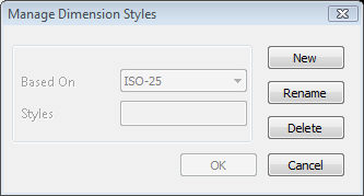
Create a new style. This can be based on any existing style from the "Based-On" selecting drop-down.
Specify the name for the new style.
Renames the selected style.
Deletes an existing style.
Closes the dialogue box without saving the changes.
Choose the layer that you want to use for the dimension. You will need to create the layer if it doesn't exist using the LaySet command.
With auto layering enabled, all dimensions will be forced to the selected layer, regardless of the active layer.
These are not the same as global styles that have already been discussed. Whereas global styles are part of the drawing and the dimension if used, user styles are system based and are just a collection of settings that can be loaded and used either individually or to modify an existing global style or to create a new one.
To use them select the one you want from the style drop-down and the select LOAD.
To save a user style, once your parameters are as required, type the name in the style box and select SAVE. If the style already exist you will be asked if you wish to over write it. Otherwise and new one will be created.
It is important to note that any settings changed on any TAB page with effect either an individual dimension or a Global style dependant on the mode selected.
If you are starting out with Caddie you may find that the only settings that need to be changed can be found on the BASIC tab. For advanced dimension settings the other tabs can be used.
As mentioned this tab only allows changes to a small number of the of the large number of dimension parameters that can be set. These will satisfy most users by most users.
Initially when Caddie is loaded the settings, as shown above for this dialogue, are pre-loaded. If at later date you want to pre-load different settings, you can do this by editing you template file (*.CTP) and changing these parameters to what you want. Then as long as you tell Caddie to use this template the dimension parameters you created will be re-loaded as your starting settings.
At the top of the BASIC tab page is a tick box to set the basic defaults. With it is un-ticked you will notice that all the fields are grayed out. The only way to change any of these settings is to go to the relevant tab and change the setting on that tab. The fields of the basic page will be still grayed out, but will now show the new values.
If any setting has been changed on an advanced tab page and that parameter is not shown on the basic page these changed parameters will still stay set when you go back to the BASIC tab page. However if you want to set all the settings back to defaults tick the "use basic settings" tick box. All the fields on the BASIC tab are now directly accessible. It is important to also note that as soon as this tick box is ticked then all settings NOT shown on this page will be re-set to the Caddie defaults.
see Template Creation and Using
A tick box as described above
Where the target scale is indicated. This is used by all other dimensions settings. Its only purpose is to act as a calculation multiplier. So for instance if the text target size was to be 3mm and the scale of the target viewport or plot is to be 1:50 any dimension text would be drawn with a size of 150mm (3mm x 50).
Sets the pen used for all dimension lines to the pen selected from this drop-down.
The distance the leader lines are extended beyond the leaders head. This does not effect any of the arrow heads, large circle, large dot, origins, triangles, and boxes which always stop at the leaders head.
This sets the distance for Datum dimensions leaders from the previous one.
Choose the required arrow head from this drop-down.
Set the target size of the arrow head by typing in the require value.
Choose the require text font from the drop-down. The only fonts available are those installed in the Windows | Fonts folder by Caddie and any other programme installed on your computer and any SHX font you have placed in the Caddie Fonts folder i.e.
C:\Program Files\CAD12\Fonts\txt.shx
The target height of the text. The actual size will be this size multiplied by the overall scale value
The pen used for the text.
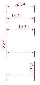
Places the text at the position selected
Above - places the text so the base of the text is next to the leader line and reads left to right and bottom to top.
Centred - places the text so the centre line of the text breaks into the leader line and reads left to right and bottom to top.
Outside - places the text so it is on the side of the leader line which is furthest away from the dimension measurement points.
JIS - places the text to JIS standard
Sets the pen used for Extension (Witness) lines.
Defines the gap (minimum gap if fixed length is used). The actual gap drawn will be the specified amount multiplied by the scale value.
If ticked, the extension (witness) lines will have a maximum length of the specified value (multiplied by the scale value). However if the definition end of the line is closer than the offset value the extension line will be foreshortened.
Length - sets the value used by fixed length extension lines, if used.
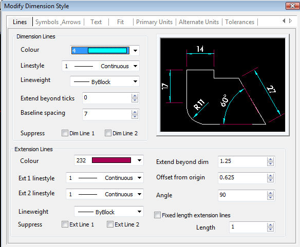
Sets the advance properties for dimension lines.
Set the pen for the dimension lines (leaders). Select the required pen from the drop-down.
Choose the required linestyle to be used for dimension lines (leaders).
Specify the line thickness here.
Specify the distance to extend the dimension line (leader) past the arrow heads.
Specify the value to use for the spacing of datum dimension lines between each other.
You can suppress the use of one or both dimension (leader) lines. You can choose which one or both to suppress.
Set the pen to be used for extension lines
Set the linestyle to be used for extension line 1
Set the linestyle to be used for extension line 2
Sets the lightweight of the extension lines
You can suppress the use of one or both extension (witness) lines. You can choose which one or both to suppress.
Allow you to specify how far past the dimension (leader) lines the extension lines will go.
Specifies the angle of the extension (witness) lines
Specifies the gap between the start of the extension from the point of measurement.
If "Fixed Extension Lines" is selected you can specify the fixed length.
Specify the length here
Settings for the was Arrows are displayed
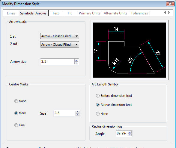
Choose from the selection which arrow head to use for each end and the size it will be.
Choose from the selection which arrow head to use for the 1st arrowhead.
Choose from the selection which arrow head to use for the 2nd arrowhead .
Specify the size to use for the arrowhead
Used for angular measurements
No marks drawn.
Creates a centre mark with a size specified with SIZE.
Creates a centre line with a size specified with SIZE.
Sets the size of Mark and Line (see above)
Places the arc symbol before the arc dimension text
Places the arc symbol above the arc dimension text
No arc dimension symbol drawn
Advanced dimension text parameters.
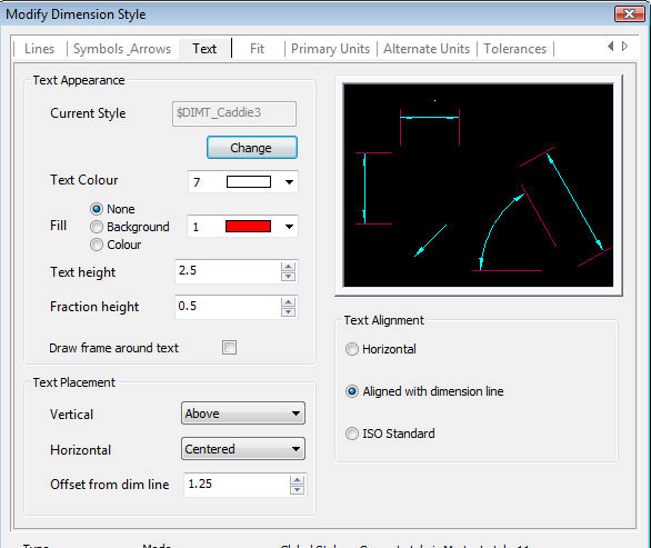
Dimensions can either use the dimension style settings or the dimension text can use a Caddie text style. The window displays the current style setting. Selecting "Change" sets the text style to be assigned for dimension text.
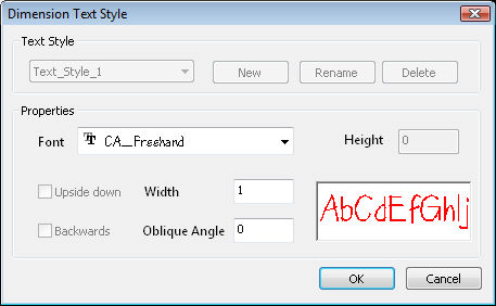
If a different style than the one displayed is required select "Change". This will the following dialogue window where you can
Select an existing style from the style list
Create a new one "NEW"
Rename an existing style "RENAME"
Delete an existing style "DELETE"
You can also override the text style parameters, these will not change the dimension style parameters but any changes made here will be used in preference to the dimension style parameters.
Choose the text pen from this list
Puts a solid background to the text, if selected.
Select from: None, Background, Colour
Dimension Text is placed without any background.
Inserts a clear area behind the text which in effect covers over any underling objects.
Similar to Background but puts a coloured, selected from the colour drop-down, background.
Sets the height of the text.
Sets the height of any fractions by a scale of the text height.
If ticked a frame is drawn around the dimension text.
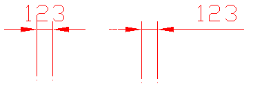
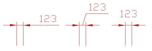
Sets the position of the horizontal dimension text with respect to the dimension line and the extension lines.
The same as on the Basic tab.
|
|
Centered - Places the text central from each end of the leader line. |
|
At Ext Line 1 - Places the text next to the 1st. witness line |
|
|
At Ext Line 2 - Places the text next to the 2nd. witness line |
|
|
Over Ext Line 1 - Places the text in-line with the 1st. witness Line |
|
|
Over Ext Line 2 - Places the text in-line with the 2nd. witness Line |
Always places the text horizontally, disregarding the dimension line (dimension leader) angle
Places the text along the dimension line (dimension leader)
Uses the ISO standard for placement
Parameters that describe how dimension will be fitted to the drawing.
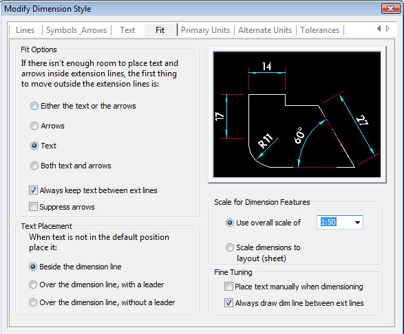
The settings used if the text is to large to fit between the extension (witness) lines. The choices are:
Either text or arrows - chooses the best fit
Arrows - only moves the arrows
Text - only moves the text
Both text and arrows - moves text and arrows.
You also have to choice to
Keep text within the extension lines or, if un-ticked outside the witness lines.
If the text can not be placed in the correct position where should it be placed? The choices are:
Besides the dimension line Over the Dimension line without a leader
Over the Dimension line with a leader
Use the overall scale with that selected from the drop-down box.
Use sheet scale is not implemented in Caddie 12. However if a drawing from another CAD system has this feature used then it would be indicated here and can be set to and overall scale.
Additional fit options can be set here.
Place Text Manually When Dimensioning - Allows the user to override the default horizontal automatic placement of text and place the text manually.
Always Draw Dim Line Between Ext Lines
If ticked dimension lines are drawn between the measured extension lines even when arrowheads are placed outside the extension lines.
Parameters for setting the format of the units and the way they are displayed.
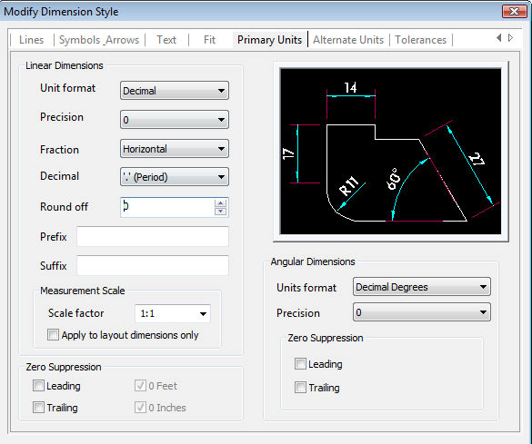
Sets the current units format for all linear dimension types.
Sets the number of decimal places in the dimension text.
Sets how fractions are displayed.
Choose what decimal separator should be used.
Sets rounding rules for dimension measurements for all dimension types except Angular
Indicates a prefix for the dimension text i.e > (>100)
Indicates a suffix for the dimension text i.e mm (100mm)
Sets a scale factor for linear dimension measurements. The dimension measurement value specified is multiplied the by the value entered here. So if you measure a value of 5 and the scaling value is 2 the value displayed is 10. This does not apply to angular dimensions or is it applied to rounding values or to plus or minus tolerance values.
Applies the linear scale value only to dimensions created in sheets. This sets the length scale factor to reflect the zoom scale factor for objects in a model space viewport.
Settings specifically for angular dimensions.
Sets the format of angular measurements.
Sets the number of decimal places the an angular measurement will use.
Controls the suppression of leading and trailing zeros, and of feet and inches that have a value of zero.
Suppresses leading zeros in all decimal dimensions. For example, 0.2500 becomes .2500.
Suppresses trailing zeros in all decimal dimensions. For example, 5.2500 becomes 5.25.Leading
Parameters for setting the way alternative units will be displayed
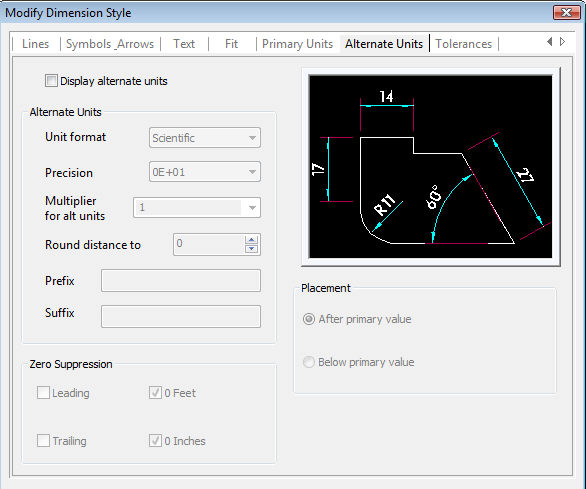
If ticked the alternative units will be used.
Sets the format of angular measurements.
Sets the number of decimal places in the dimension text.
Specifies a multiplier to use as the conversion factor between primary and alternate units. To determine the value of alternate units, all linear distances (measured by dimensions and coordinates) are multiplied by the current linear scale value.
The length scaling value changes the generated measurement value. The value has no effect on angular dimensions,rounding values or the plus or minus tolerance values.
Sets rounding rules for alternate units for all dimension types (excluding angular measurements).
If you enter a value of 0.25, all alternate measurements are rounded to the nearest 0.25 unit. Similarly, if you enter a value of 1.0, all dimension measurements to the nearest integer.
The number of digits displayed after the decimal point depends on the Precision setting.
Indicates a prefix for the alternative dimension text i.e > (>100)
Indicates a suffix for the alternative dimension text i.e mtr (100mtr)
Controls the suppression of leading and trailing zeros, and of feet and inches that have a value of zero.
Suppresses leading zeros in all decimal dimensions with the alternative units. For example, 0.2500 becomes .2500.
Suppresses trailing zeros in all decimal dimensions with the alternative units. For example, 5.2500 becomes 5.25.Leading
Places alternate units after the primary units.
Places alternate units before the primary units.
Settings for displaying the way tolerances are displayed.

|
|
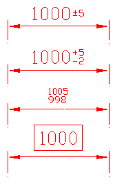
NoneNo Tolerances are used. |
SymmetricalAfter the measurement a plus and minus sign is added (±) and the value following is both the upper and lower value. |
|
DeviationAfter the measurement follows the tolerance deviations on two lines. The top (+) is the upper value and the lower (-) is the lower value. |
|
LimitsInstead of displaying a value followed by a tolerance, when limits is used the actual values of upper and lower limits are place one over the other. |
|
BasicThe dimension value is drawn with a rectangle around the text. |
Specify the number of decimal places here.
Specify The upper value here
Specify the lower value here (symmetrical and deviation only).
Sets the text height as a scale vale of the text height.
Set the alignment of the tolerance text with respect to the dimension text. The choices are Middle, Top & Bottom.
Controls the suppression of leading and trailing zeros, and of feet and inches that have a value of zero.
Suppresses leading zeros in all decimal dimensions with the alternative units. For example, 0.2500 becomes .2500.
Suppresses trailing zeros in all decimal dimensions with the alternative units. For example, 5.2500 becomes 5.25.Leading
Suppresses the feet part of the text when the value is less than one foot.
Suppresses the inch part of the dimension text when the value is multiples of a whole foot (1'-2", 1').
For the alternative unit specify the number of decimal places here.
Controls the suppression of leading and trailing zeros, and of feet and inches that have a value of zero for the alternative units.
Suppresses leading zeros in all decimal dimensions with the alternative units. For example, 0.2500 becomes .2500.
Suppresses trailing zeros in all decimal dimensions with the alternative units. For example, 5.2500 becomes 5.25.Leading