- +27 12 644 0300
- +44 1234 834920
- This email address is being protected from spambots. You need JavaScript enabled to view it.
AEC
Industrial Units Made Easy


- Category: AEC
- Thursday, 10 July 2014 15:15
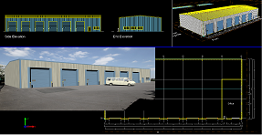
Industrial Unit in ~10 minutesWatch the YouTube video and
|
||||
|
Discover how you can start producing; Plans of your Industrial Unit designs in minutes with short YouTube Video Guide
|
|
|||
Multi-Panel DWA Door
- Category: AEC
- Monday, 26 October 2015 15:15
New and Updated Caddie Multi-Panel Door DWA Style with Integral Cill |
|
Download the Multi-Panel DWA HEREDownload Caddie Evaluation HEREPlease Note that not all Web Browsers support this link, so if you are presented with a page of text and symbols, try an alternative Browser. And please feel free to forward this link to any friends or colleagues who might be interested too. |
Magic Schedule Bullet
- Category: AEC
- Thursday, 10 July 2014 15:15
Watch the Tutorial Video and
|
||||
|
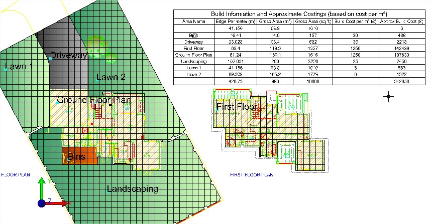
Use Your Existing Drawings: Watch the YouTube video See how to create smart schedules and cost estimates from existing plans saving time and reducing errors |
|
|||
Watch the Video and get the DownloadWatch the YouTube video showing how to create the smart schedules from your existing plans, how to update your cost estimates, label the areas you schedule, and keep your plans and schedules in sync to minimise errors. Download the Caddie Magic Schedule Bullet HERE and try it for yourself... Download a FREE Evaluation copy to try on your own projects. |
||||
Configure AEC Door Types (2)
- Category: AEC
- Thursday, 10 July 2014 15:15
|
Watch the Tutorial Video and |
||||
|
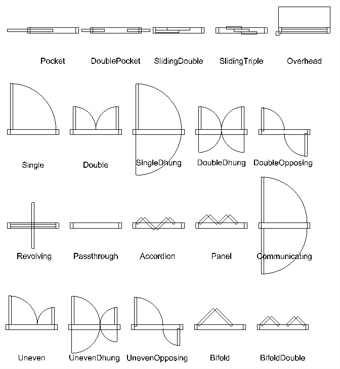
Subject: Step-by-step easy to follow guide Why watch: Learn how to set the door type and configure AEC doors styles to use when drawing floor plans and AEC modelling.
Step-by-step easy to follow guide |
|
|||
|
'WOW! I was amazed by just how easy Caddie 20’s ‘AEC Build’ tools are to use, and genuinely gobsmacked at the results I was able to produce in such a short space of time. In just over 20 minutes I managed to produce a complete model of my building, even including the roof, which I could view in the form of plans, elevations, or full-on 3D model.' Peter Fishenden for Quantus Developments Ltd.
And much more - New features in Caddie 20 Download a FREE Evaluation copy to try on your own projects. |
||||
Step-by-step guide to creating Door Window Assemblies (DWA) (2)
- Category: AEC
- Thursday, 10 July 2014 15:15
Watch the Tutorial Video nowStep-by-step guide to creating Door Window Assemblies (DWAs) |
|
|
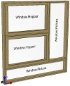
Subject: Create your own DWAs Step-by-step easy to follow guide Why watch: Learn how to create your own Door Window Assemblies to model any combination of Doors and Windows for use as multi-panelled windows, shop fronts and more |
|
|
'WOW! I was amazed by just how easy Caddie 20’s ‘AEC Build’ tools are to use, and genuinely gobsmacked at the results I was able to produce in such a short space of time. In just over 20 minutes I managed to produce a complete model of my building, even including the roof, which I could view in the form of plans, elevations, or full-on 3D model.' Peter Fishenden for Quantus Developments Ltd.
And much more - New features in Caddie 20 Download a FREE Evaluation copy to try on your own projects. |
|
Vector Linestyles Change Scales According to Annotation Scale When Read Into Other Systems
- Category: AEC
- Wednesday, 02 January 2013 16:20
Question:
When a drawing created in Caddie is worked on in some other DWG based systems the linestyle scales of the vector lines sometimes changes with the annotation scale in the modelspace. Can we stop this happening?
Applies To:
Caddie 17 onwards
Answer:
Yes you can. The newer versions of DWG support a system variable called MSLTSCALE. If this is set to False then the linestyles do not scale in the modelspace whereas if you set it to True then they will scale in some software. You can change it in Caddie by going to Utilities -> System -> Set System Variable then following the prompts on the command line, or it can be changed in other fully DWG compatible software by their equivalent tools.
Copying Window, Door and DWA Properties
- Category: AEC
- Tuesday, 14 February 2012 12:31
Applies to:
Caddie 17 and later
Question:
I have already drawn a Window using the parameters that I want. Do I have to type in the same parameters again or is there some way of 'getting' those parameters and using them for new windows?
Answer:
In Caddie 17 and beyond, on the bottom right of the Window / Door / DWA dialogues there is a button labelled 'Get Parameters' If you click this button, you can then click on any Window / Door / DWA and Caddie will extract the parameters and populate the dialogue for you, saving you having to type them in.
Alternatively you can select the existing Window / Door / DWA, right click and from the CSM select 'Copy'. Caddie will create an exact copy in the location that you choose.
Can I easily add a railing to a helical stair?
- Category: AEC
- Monday, 26 September 2011 14:37
I have used the AEC tools to create a helical staircase but I can't see how to create a railing that follows the profile of the stairs.
If you select the stair, then right click, and from the context sensitive menu choose AEC -> Railing. To determine different parameters for the railing you can use AEC style manager to edit an existing railing style or create a new one.
Applies to:
Caddie 16 onwards
Can I add holes to roof slabs?
- Category: AEC
- Monday, 26 September 2011 14:32
How can I create a hole in a roof slab?
In the AEC -> F/S/R menu there is a command called 'Hole'. This can be used to add holes to either floor or roof slabs.
See this video which includes how to do this
{youtubejw width="560" height="315"}qKOitRqCki4{/youtubejw}
How Can I Draw AEC Walls on Different Levels?
- Category: AEC
- Tuesday, 26 April 2011 18:20
Applies to:
Caddie 16 and later
Question:
I am drawing a building that requires different walls for each floor. How can I change heights and what are the consequences for other objects such as doors and windows?
Answer:
AEC walls in Caddie are drawn on the current UCS. To draw a wall at a different baseline height, first change the height of the UCS.
To change the height of the UCS go to the 3D tools and select UCS.
At the top of the list there is an OFFSET tool. If you don't know where the current UCS positions is first select the WORLD command. This will put the UCS back to the WCS position.
For the Offset command dialogue change the height to the required value or you could use PICK to select the top of an existing wall.
If you intend to reuse these settings, use the SAVE and RECALL UCS commands at the bottom of the same toolbar.
With the UCS in the new position you can draw walls which will have their base height on the new UCS position.
How does this affect windows and doors etc.
Windows and doors are drawn with the head height referencing the baseline of the wall in which they are to be placed.
So if a window, door or opening is to be inserted in the newly positioned first floor wall, the head height will be, say, 2100mm. If the same window was to be placed in a two floor height wall the head height may be 4500mm.
You can control which part of the wall the door / window etc. is anchored to by selecting it then choosing 'Anchor' from object properties.
Controlling Hatch Display for Walls
- Category: AEC
- Wednesday, 15 December 2010 14:47
APPLIES TO
- Caddie 15 onwards
QUESTION
How can I control whether hatch is shown in different wall components in plan?
ANSWER
The hatch will normally be controlled by the material assigned to the component.
Go to AEC -> AEC Style Manager. Select Multi-purpose Objects -> Material Definitions -> Material (where Material is the material definition to change)
Click General then Properties and choose the ‘Layer/Color/Linetype’ tab. Click the ‘Yes (or No) to the right of ‘Plan Hatch’ and at the top of the column choose change the yes to no (or no to yes to switch it on). Click Apply then Close. Finally click Close again to return to the drawing.
Regen the modelspace and the hatch should now be switched off (or on) in that component.
OTHER FAQ's
How Can I Stop AEC Walls From Doing a Cleanup When Drawing an Extension to an Existing Building
- Category: AEC
- Thursday, 07 April 2011 18:58
Applies To:
Caddie 16 and above
Question:
I am adding an extension to an existing building, but the walls cleanup (merge) with those of the existing building. How can I stop this happening?
Answer:
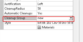
Walls only clean-up witt other walls in the same Cleanup group. So all that needs to be done is to create a new Cleanup group and assign the NEW walls to that group.
Using AEC Style Manager from the AEC menu go to the section as shown below:
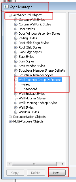
Select the wall Cleanup Group Definitions text and create a New group with whatever name you want.
Once done just reassign the new walls to this group in object properties and the walls will no longer merge.
How Do I Create and Change AEC Materials
- Category: AEC
- Thursday, 24 February 2011 17:49
Applies To:
Caddie 16 with Vio
Question
How do I create and change AEC materials used with Vio rendering?
Answer
The best way to render in caddie is to use the, add-on, Vio rendering commands.The description below requires the Vio rendering commands. Assigning renders to standard 3D objects can be done by using the materials tools in the Vio commands. Normally a material would be created and then the material attached to a 3D object by selection, layer, etc. When it comes to AEC objects a different approach has to be taken..
How To Change "db" Materials
All AEC objects are created using styles. If we look at a wall for instance, the wall style may consist of a number of wall components, Brick, Cavity, Insulation, Block and Plaster etc. Each of these components will have been assigned a render when the style was created. To give the user a head start, the standard wall styles already have a render assigned. It is likely that the style will just be a flat colour as a representation, but never the less a quick render could be produced.
All of the currently assigned AEC renders will show in the Materials dialogue once they have been loaded. There are basically two ways these can be loaded.
- The first time the render command is used with AEC object present in the drawing
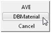
- Using the Convert Materials Command and selecting DBMaterials from the dropdown
|
Once loaded by either of these methods, the materials dialogue will display the AEC materials as shown. |
|
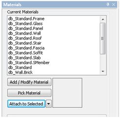
As already mentioned, the normal Pick Material and Attach to Selected buttons are not used with AEC objects. It is the style of the object that assigns the material.
How do we know what materials are used for a particular AEC object.
This can be done by either using the AEC Style manager from the AEC menu or easier is to select the object and from Object Properties select the material option.
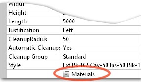
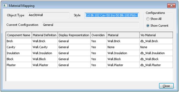
We can’t change the materials here; this dialogue is just used to identify which of the numerous materials is used for a particular component.
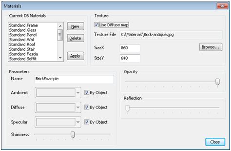
Once we know the material we can change it. The easiest material to apply is an image material. This will normally be an .JPG image and can be sourced either from materials supplied with Caddie, your own images or from one of the various internet sites. We will look to change to a pre-defined materials see later in this article.
To change the material for the brick component in the above example, select the db_Wall.brick material from the materials dialogue.
|
|
|
You will notice the current base colour and a reflective colour render for this component has already been pre-set |
|
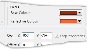
- Tick the Update Texture File tick box
- Browse to the image you want to use
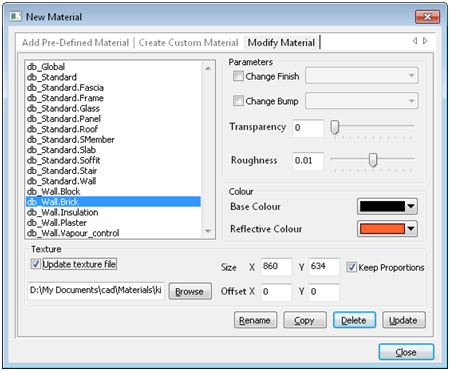
- You will notice the Path and file details have now been entered
- Change the size. By default the size is the actual pixels of the image. However a good rule of thumb is to work out the physical size in millimetres and convert this to pixels. For instance if the image shows 4 bricks wide this would equate to 860mm so enter 860 in the x value. If the Keep Proportions tick box is set, the Y direction will be automatically calibrated
- The Transparency and Roughness can be changed if required
- Select the Update button. The base colour will change, however we are not using it, so it can be ignored
- If you need to, change any other materials by selecting the material and change as above
Now when a render is performed the final rendered image will show the brick in the chosen texture.
Note that all wall styles using this changed “db” material will also be changed. If you require a different texture for some walls, a new style will have to be created and a new material assigned to the component in the AEC Style Manager.
How do I change the material to an internal texture?
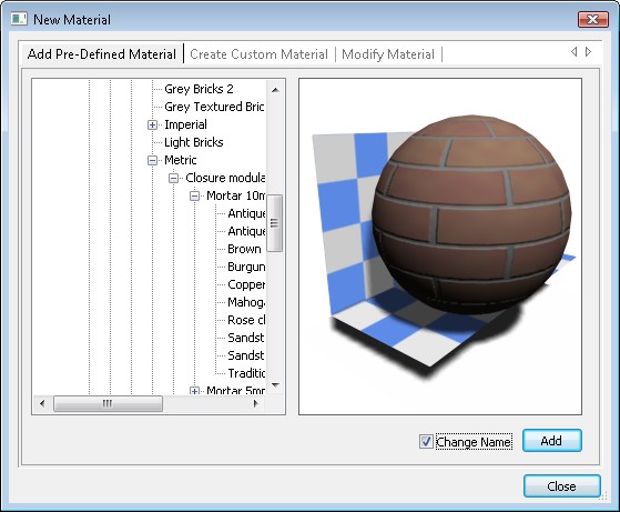
Vio has a number of pre-defined materials libraries available. These are accessed from the first tab in the materials dialogue. to modify an existing Pre-Defined material a different method has to be used.
- Select the "Add Pre-Defined Material" tab
- Choose the required material
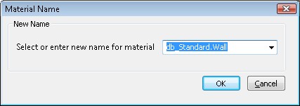
- Tick the tick box "Change Name"
- Select the " ADD" button
- From the Material name drop down select the name of the material that you want to change
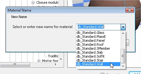
- Select "OK"
- Say "YES" to the Overwrite Material dialogue
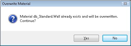
- If you don't need to change any other materials, select "Close" from the initial dialogue.
Basically what you have done is to create a replacement material called db_Standard.Wall
Creating An AEC Material
|
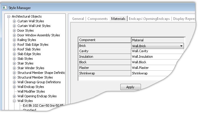
As mentioned AEC objects are defined by their styles. Part of the process in creating a wall is to assign a material to the styles components. With the wall style selected choose the Materials tab. Against each component there is a materials drop down. From this you can select any named material.
|
|
|
If you need to create a new material move down the left menu and expand Multi Purpose Objects and select Material Definitions. Here you will see NEW at the bottom of the list. The name of this material will default to MaterialDefinition_n, where n is an incremental number. The name can be changed by selecting the General tab.
|
|
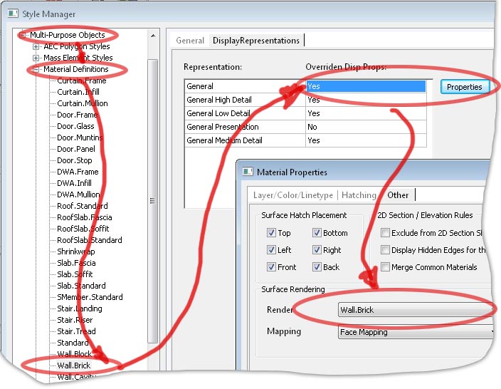
From the Display Reprsentions tab, if there is a NO in the field double click it to change it to YES then, select the Properties button.
In the subsequent dialogue give a name to the material and select the the parameters, such as Diffuse Map (the texture image) or just select an Ambient colour and set any of the other properties. These can of course be change later as has already discussed.
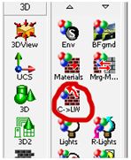
Select Close, Apply in the previous dialogue and close the AEC Style Manager. To see the material in the materials dialogue refresh the list by using the C>LW command as mentioned above.
How can I add new objects to an existing AEC section?
- Category: AEC
- Wednesday, 20 October 2010 14:06
If you create new AEC objects and want to include them in an existing section or elevation, then you select 'Regen Section'. Select the section to be regenerated and from the dialogue box click the 'Select' button:
select the additional objects with a rectangular selection box then click OK to regenerate the section.
How can I show door swings on an AEC horizontal section (plan)?
- Category: AEC
- Wednesday, 20 October 2010 11:34
By default, AEC sections don't show the door swings. If you want to switch them on, do the following:
Open the drawing.
Open AEC display manager. Select Sets -> Section_Elev and set Plan to ‘Yes’, by double clicking the cell.
See figure below:
How can I turn off the mitre lines between walls on AEC sections?
- Category: AEC
- Wednesday, 20 October 2010 11:24
To switch the mitre lines off:
There a two main ways of turning the mitres on or off.
Globally this may be done using the Display Manager. Note this method may also turn other (wanted0 elements on or off.
Open the drawing.
Open the display manager. Select Representations By Object -> 2D Section/Elevation -> General, and set Defining Line to ‘No’.
Regenerate the Sections. See figure below:
The second method uses the properties of the materials to decide if to show the material junction or not.
Using this method you can get Caddie to force the removal of joins to common material. So for instance if two walls use the same material then Caddie will turn off the join.
To access this property, open the AEC Style Manage.
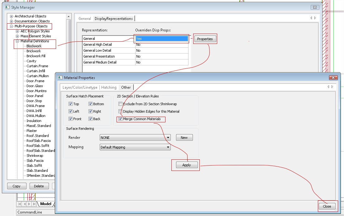
From Material Definitions, find the material that needs changing. Make sure the general section allows overrides by double clicking it. The select "Properties". In the Materials Properties dialogue select the "Other" tab and tick the "Merge Common Materials" tick box. and "Apply". Close the dialogue. Refresh the section and do a Regen. You will find all the materials changed and joining will now have the mitres removed.
How can I turn the hatch off on an AEC Section or Elevation?
- Category: AEC
- Wednesday, 20 October 2010 11:15
By default, AEC sections and Elevations will be created hatched. If you want to switch off the hatch do the following:
Open the drawing.
Open AEC display manager. Select Representations By Object -> 2D Section/Elevation -> General and set section hatch to ‘No’.
See figure below:
AEC Sections with auto-place roof tiles FP
- Category: AEC
- Monday, 26 October 2015 15:15
Automated AEC Sections with additional 2D auto-place roof tiles |
|
|
|
Please Note that not all Web Browsers support this link, so if you are presented with a page of text and symbols, try an alternative Browser. And please feel free to forward this link to any friends or colleagues who might be interested too. |
AEC Sections with auto-place roof tiles
- Category: AEC
- Monday, 26 October 2015 15:15
Automated AEC Sections with additional 2D auto-place roof tiles |
Caddie auto insert,align and repeat roof tile symbols Download HERE
|
|
|
Please Note that not all Web Browsers support this link, so if you are presented with a page of text and symbols, try an alternative Browser. And please feel free to forward this link to any friends or colleagues who might be interested too. |
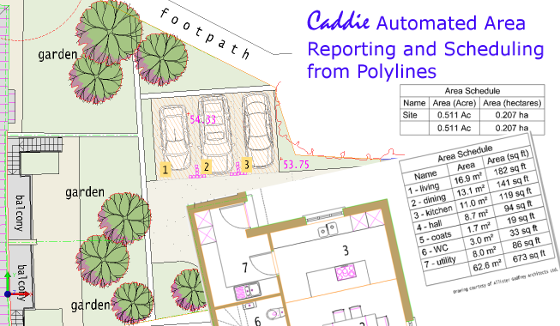
Automated Area Scheduling
- Category: AEC
- Monday, 26 October 2015 15:15
Automated Area Scheduling from Polylines |
 |
|
Download Automated Area Schedule Styles HEREDownload User Guide HEREDownload Caddie Evaluation HERE |
|
|
|
Please Note that not all Web Browsers support this link, so if you are presented with a page of text and symbols, try an alternative Browser. Forward these links to any friends or colleagues who might benefit from Caddie Auto-reporting and scheduling.
|